


Installation
6 720 805 339 (2014/09)
14
3.7.5
DHW expansion vessel
▶ Connect the expansion vessel using a rigid pipe connections (e.g..
copper) to the cold water inlet control group.
For DHW systems with a large volume:
▶ Check whether the expansion vessel supplied (12, 18 or 25 litres) is
adequate and if required, install an additional expansion vessel in
parallel to the one supplied, ensuring the air charge of each is
identical.
3.7.6
Installing the discharge pipe work from the safety valves
supplied
▶ Locate the cold water inlet control group so that any water flowing
from the expansion relief anti-vac valve will be drained together with
any water discharged from the temperature and pressure relief
valve.
▶ Route the discharge pipework in accordance with part G3,
schedule 1 of the Building Regulations (the following includes the
most important requirements of the Building Regulations).
▶ Install the tundish vertically in direct proximity to the cylinder
(maximum distance between safety valves and tundish 600 mm).
▶ The discharge pipe work must be of a material capable of
withstanding the potential temperatures and pressures.
▶ The following applies for the discharge pipe work downstream of the
tundish:
– Minimum 300 mm vertical drop before the first bend.
– Must be at least one pipe size larger than the inlet of the tundish.
– Route the discharge pipe work with a constant fall.
3.7.7
Discharge Arrangement
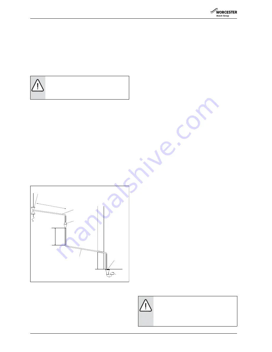
Fig. 10 Diagram of a typical discharge pipe arrangement (extract from
Building Regulation G3)
A
Safety device (e.g. temperature relief valve)
B
Metal discharge pipe (D1) from temperature relief valve to
tundish
C
Discharge pipe (D2) from tundish with continuous fall
D
Fixed grating
E
Trapped gulley
F
Tundish
Position the inlet control group so that the discharge from both the two
safety valves can be joined together via a 15 mm end feed Tee. Connect
the Tundish and route the discharge pipe. The discharge pipework must
be routed in accordance with Part G3 of schedule 1 of the Building
Regulations. The information that follows is not exhaustive and if you are
in doubt you should seek advice.
The two safety valves will only discharge water under fault conditions.
When operating normally water will not be discharged.
The tundish should be vertical, located in the same space as the
unvented hot water storage system and be fitted as close as possible and
within 600 mm of the safety device e.g. the temperature relief valve.
The discharge pipe (D2) from the tundish should terminate in a safe place
where there is no risk to persons in the vicinity of the discharge and:
• Be at least one pipe size larger than the nominal outlet size of the
safety device unless its total equivalent hydraulic resistance exceeds
that of a straight pipe 9 m long i.e. discharge pipes between 9 m and
18 m equivalent resistance length should be at least two sizes larger
than the the nominal outlet size of the safety device, between 18 and
27 m at least 3 sizes larger, and so on. Bends must be taken into
account in calculating the flow resistance. Refer to Fig. 10, Table 8
and the worked example.
An alternative approach for sizing discharge pipes would be to follow
British specification standards for design installation, testing and
maintenance of services supplying water for domestic use within
buildings and their curtilages.
• Have a vertical section of pipe at least 300 mm long, below the
tundish before any elbows or bends in the pipework.
• Be installed with a continuous fall.
• It is preferable for the discharge to be visible at both the tundish and
the final point of discharge but where this is not possible or
practically difficult there should be clear visibility at one or other of
these locations. Examples of acceptable discharge arrangements
are:
– Ideally below the fixed grating and above the water seal in a
trapped gulley.
– Downward discharges at a low level; i.e. up to 100 mm above
external surfaces such as car parks, hard standing, grassed areas
etc. are acceptable providing that where children play or
otherwise come into contact with discharges, a wire cage or
similar guard is positioned to prevent contact whilst maintaining
visibility.
– Discharges at a high level; e.g. in to metal hopper and metal down
pipe with the end of the discharge pipe clearly visible (tundish
visible or not) or onto a roof capable of withstanding high
temperature discharges of water and 3 m from any plastic
guttering systems that would collect such discharges (tundish
available).
– Where a single pipe serves a number of discharges, such as in
blocks of flats, the number served should be limited to not more
than 6 systems so that any installation can be traced reasonably
easily. The single common discharge pipe should be at least one
pipe size larger than the largest individual discharge pipe to be
connected. If unvented hot water storage systems are installed
where discharges from safety devices may not be apparent i.e. in
dwellings occupied by blind, infirm or disabled people,
consideration should be given to the installation of an
electronically operated device to warn when discharge takes
place.
WARNING:
Risk of scalding!
Hot water can lead to severe scalding.
▶ Route the discharge pipe work so that any
discharged hot water or steam cannot create a risk.
A
B
C
D
E
F
6 720 645 525-14.1O
600 mm
maximum
300
m
m
minimu
m
▶ The discharge may consist of scalding water and
steam. Asphalt, roofing felt and non-metallic
rainwater goods may be damaged by such
discharges.
▶ It is not acceptable to discharge straight into a soil
pipe.


