background image

Original operation manual 

AIRCOMBI


27

AirCombi_BAoDB_en_1701 •  rs

Transport, installation and assembly

Safety measures at the place of installation:


This machine requires a solid base and sufficient free space for safe 

operation.


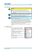
Always keep the working area, especially all walkways and standing 


areas, clean and tidy. Immediately remove any spilled material and 

cleaning agent.


Always ensure adequate ventilation at the work place to avoid damage 

to health and material objects. Always ensure an air change rate of at 

least 5.


Always observe the processing instructions issued by the material 


manufacturers.


Even though there are no legal directives for low-mist Airless spraying 

methods, all hazardous solvent vapours and paint particles should be 

extracted.


Protect objects adjacent to the spraying object against possible damage 

caused by the material mist.

4.3  Assembly

WARNING

If assembly work is carried out by people who have not been trained for 

this work, they endanger themselves and other people and impair the 

safety and reliability of the machine.


Electrical components must only be mounted by trained qualified elec-

tricians – with all the other components, e.g. the spray hose and the 

spray gun being assembled by trained personnel only.

WARNING

Sources of ignition may result from assembly work (e.g. through mechanical 

sparks, electrostatic charge, etc.).


Carry out all installation and maintenance work outside of areas with 

explosive atmospheres.


Assemble the parts or fittings dismantled for transport purposes before 

start up and in compliance with the intended use of the system.


Ensure that the compressed air shut-off valves are closed and all air 

pressure regulators have been fully turned down before carrying out any 

installation work.

Summary of Contents for AIRCOMBI Phoenix 6530

Page 1: ...AIRCOMBI DEVICES Original operation manual AIRCOMBI AirCombi_DBK_en_1701 rs Operation manual Serial number __________________ Series PROFIT PHOENIX Design size __________________ ...

Page 2: ...2 Original operation manual AIRCOMBI AirCombi_DBK_en_1701 rs ...

Page 3: ...and maintenance personnel 16 2 5 1 Machine owner s duties 16 2 5 2 Personnel qualification 16 2 5 3 Authorized operating personnel 16 2 5 4 Personal Protective Equipment 16 2 6 Notes on warranty 17 2 6 1 Conversions and alterations 17 2 6 2 Spare parts 17 2 6 3 Accessories 18 2 7 Emergency procedures 18 2 7 1 Stop the machine and release the pressure 18 2 7 2 Leakages 18 2 7 3 Injuries 18 3 Machin...

Page 4: ...3 5 4 Material change 34 5 5 Releasing pressure 35 5 6 Interruptions to work 35 5 7 Decommissioning 35 5 8 Disposal 36 6 Maintenance 37 6 1 Regular inspections 38 6 2 Maintenance plan 38 6 3 Maintenance unit 39 6 3 1 Checking the lubricant level in the fog oiler 39 6 3 2 Checking and adjusting the fog oiler 40 6 3 3 Checking and cleaning the water separator 40 6 4 High pressure pump 41 6 4 1 Toppi...

Page 5: ...Contents Original operation manual AIRCOMBI 5 AirCombi_BAoDB_en_1701 rs 8 Technical data 47 8 1 PROFIT series 47 8 2 PHOENIX series 47 8 3 Machine card 48 8 4 Type plate 48 ...

Page 6: ...49 6441 609 50 Email info wiwa de Website www wiwa de These operating instructions are intended exclusively for the preparation operating and maintenance personnel It is expressly prohibited to distribute these operating instructions duplicate exploit or communicate their contents unless expressly authorised to do so Infringement will lead to compen sation All rights to any patent utility model or...

Page 7: ... operation manual You should have read and understood the guidelines and accident prevention regulations that apply in your country In Germany these are as follows BGR 500 chapter 2 29 Application of Coating Materials BGR 500 chapter 2 36 Working with Fluid Spraying Equipment published by the employers liability insurance association for the gas remote heating and water management sectors We stron...

Page 8: ...understood the operation manual beforehand especially the chapter entitled Safety Your safety is at stake We recommend to the owner of this machine to have this confirmed in writing 2 1 Explanation of symbols Safety notes warn you of potential risks of accidents and tells you the mea sures that are required to prevent accidents In WIWA operation manuals safety notes are specially highlighted and m...

Page 9: ...the requirement to wear protective goggles to protect against eye injuries caused by gases fumes or dust Wear ear defenders Indicates the requirement to wear ear defenders to prevent your hearing from being damaged by noise Use a respiratory protection mask Indicates the requirement to use a respiratory protection mask to prevent your respiratory tract from being damaged by gases fumes or dusts We...

Page 10: ...l hoses and hose assemblies must comply with the maximum working pressure including the required safety factor Material hoses must be leak tight and free of kinks signs of abrasion or bulges Hose connections must be tight 2 2 2 Risks caused by the spray jet WARNING The material is discharged from the spray gun under very high pressure Due to its cutting effect the spray jet can cause severe injuri...

Page 11: ...rom WIWA are conductive and designed for our machines Use only electrically conductive accessories accessory parts WARNING If the machine is contaminated by material during operation the increased coating thickness can lead to electrostatic charging Static discharges can cause fire and explosion Clean the machine immediately to remove any contamination Carry out cleaning work outside areas with ex...

Page 12: ...licable stipulations according to ATEX Please note that some parts have their own type plate with separate labelling according to ATEX In this case the lowest explosion protection of all labels displayed applies to the entire machine For applications whereby a failure of the machine could lead to dangers to personnel the owner is required to implement appropriate safety measures If agitators heate...

Page 13: ...ara doğrultmayın Pistoletu natryskowego nie kierować w stronę ludzi lub zwierząt Rikta inte sprutpistolen mot människor eller djur Não direccionar a pistola de pintura para pessoas ou animais Nicht in den Spritzstrahl fassen Do not reach into the spray jet Ne pas toucher au jet No interceptar el chorro de pulverización Не прикасайтесь к струе распыляемого материала Püskürtme huzmesine elinizi sokm...

Page 14: ...ff valve Ground cable Checklist on the depressurized machine 5 5 Lead seal on the safety valve still intact 5 5 Safety valve free of external damage 5 5 Ground cable free of damage 5 5 Operability of compressed air shut off valve correct Checklist on the pressurized machine 5 5 Function of safety valve correct When checking further safety features observe the operation manual for the optional acce...

Page 15: ...al 2 4 2 Compressed air shut off valve The compressed air shut off valve enables immediate shutting down of the machine Das Funktionsprinzip Open set in the direction of flow Close set across the direction of flow Fig 3 Compressed air shut off valve OPEN Fig 4 Compressed air shut off valve CLOSE After shutting off the air the machine is still pressurized This means that before carrying out mainten...

Page 16: ...ade between two groups of people depending on their qualifications Instructed operators have been verifiably instructed by the machine owner in the activities they are tasked with and the potential risks connected with them in the case of incorrect behaviour Trained personnel have been instructed by the machine builder so that they are capable of carrying out maintenance and repair work on the sys...

Page 17: ...essure setting and correct working methods Wear protective gloves Wear antistatic protective gloves When processing heated materials you must wear lower arm protection in addition to protective gloves to prevent burns Wear protective footwear Wear antistatic protective footwear to prevent injuries to the feet due to objects that may fall drop or roll around and to prevent slipping on a slippery fl...

Page 18: ...essure release for the machine This procedure is not suitable for decommissioning The machine has not been flushed For controlled decommissioning please see chap 5 7 Decommission ing on page 35 After remedying the emergency the machine has to be flushed see chap 5 3 Flushing on page 33 Pay attention to the potlife of the material used 2 7 2 Leakages WARNING In case of leakages material can escape ...

Page 19: ...ard or on the type plate 3 1 Intended use The AirCombi devices of WIWA are only suitable for spraying of coating and ancillary materials for surface treatment The AirCombi spraying process is ideal for very fine painting tasks covering large areas and for shaped or small workpieces The devices are primarily used in trade workshops such as carpenter s work shops for coating wood but also in the ind...

Page 20: ...uipment is modified removed or bypassed spare parts are installed that were not manufactured or delivered by WIWA see 2 6 2 on page 17 accessories are used that are not suitable for the machine see chap 2 6 3 on page 18 machines without Ex identification are used in potentially explosive atmo spheres the machine is operated outside of the operating limits according to the type plate 3 3 Machine de...

Page 21: ... 3 Air motor 4 Material pump 5 Cart 6 Carrying handle 7 Compressed air shut off valve 8 Compressed air connection 9 High pressure filter for more information see chap 6 5 on page 42 10 Drain valve for pressure release 11 Connection for spray gun and spray hose 12 Material inlet suction here suction pipe with suction strainer Design variants Fig 8 PROFIT on tripod Fig 9 PROFIT on 20 l container wit...

Page 22: ... 1 3 8 Fig 12 AirCombi PHOENIX on cart No Description 1 Dual air pressure regulator see chap 3 4 2 Cart 3 Material pump 4 Muffler 5 Air motor 6 Overflow 7 High pressure filter 8 Drain valve for pressure release 9 Material hose connection 10 Material inlet suction Design variants min 10 cm Fig 13 PHOENIX on wall bracket ...

Page 23: ...nstead of the dual air pressure regulator see chap 3 5 Fig 14 Dual air regulator 6 7 1 3 5 4 2 No Designation 1 Compressed air shut off valve 2 Compressed air connection 3 Atomizer air hose connection 4 Pressure gauge for displaying the atomizer air pressure 5 Pressure gauge for displaying the air inlet pressure 6 Air regulator for air inlet pressure to the high pressure pump 7 Air pressure regula...

Page 24: ... regulators with out maintenance unit see chap 3 4 11 9 10 Fig 16 Maintenance unit from the back Fig 17 Maintenance unit from the front 7 1 8 4 3 6 5 2 No Description 1 Compressed air shut off valve 2 Compressed air connection 3 Air regulator for air inlet pressure to the high pressure pump 4 Air regulator for atomizer air pressure 5 Filler hole for pneumatic oil 6 Setting screw for metering the o...

Page 25: ...bserve and follow the separate operation manual for the spray gun Fig 18 WIWA AirCombi spray gun Optima 2100 3 6 2 Material fluid heater Material fluid heaters can optionally be used as Heaters for the spraying material only for Airless devices see separate operation manual Auxiliary heaters for long hoses Heating spraying air for the AirCombi spraying process Observe and follow the separate opera...

Page 26: ...spended loads or inside the loading area There is a risk of death Secure the load on the transport vehicle against slipping and falling off If the machine had already been in operation please observe the following Disconnect the entire power supply even for short transportation dis tances Empty the machine before transportation fluid residues may escape during transportation despite this measure R...

Page 27: ...djacent to the spraying object against possible damage caused by the material mist 4 3 Assembly WARNING If assembly work is carried out by people who have not been trained for this work they endanger themselves and other people and impair the safety and reliability of the machine Electrical components must only be mounted by trained qualified elec tricians with all the other components e g the spr...

Page 28: ...al escaping under high pressure can cause injuries and material damage Do not use the hoses for lifting or pulling the device WARNING Components that do not comply with the maximum permitted operating pressure of the machine can burst and cause serious injury Check the maximum permitted operating pressure of the material hose and the spray gun before assembly It must be greater than or equal to th...

Page 29: ...at the machine has been properly grounded outside of explosive atmosphere areas Also ground the object to be coated 1 Connect the ground cable of the machine to an electrically conductive object outside explosive atmosphere areas 2 Ensure proper grounding of the object to be coated 4 3 4 Connect compressed air The compressor capacity must match the air requirements of the machine and the diameters...

Page 30: ...shut off valve is closed the air regulator has been turned down fully 2 Connect the air hose to the air inlet of the pressure regulator see Fig 22 or to the maintenance unit see Fig 23 depending on the version Fig 22 Connecting compressed air to the dual air pressure regulator Fig 23 Connecting compressed air to the maintenance unit ...

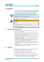
Page 31: ...tures are installed and fully operational Before initial commissioning remove the adhesive label Remove before use or the vent plug from the overflow Check the level of lubricant in the oil container of the maintenance unit if fitted and top up if required see chap 6 3 1 Checking the lubricant level in the fog oiler on page 39 Check the level of release agent on the pump and top up if necessary se...

Page 32: ...sufficient spraying pressure results in the appearance of streaks and differences in the coating thickness 30 40 cm Fig 24 Spraying distance 1 2 No Designation 1 Flat jet control left atomizer air ON large volume of air high level of atomizing right atomizer air OFF small volume of air low level of atomizing 2 Round jet control lateral addition of atomizer air Fig 25 Regulating the atomizer air St...

Page 33: ...t wave wrong Area to be coated thin layer thin layer thick layer Worn nozzles cause higher material consumption and have a negative effect on the quality of coating 5 3 Flushing Flushing the machine is necessary during the initial commissioning so that the spray material is not influ enced by the test medium with which the machine was tested in the factory for faultless function when changing mate...

Page 34: ...t residue 8 Place the suction pipe into the container with the cleaning agent 9 Open the compressed air shut off valve 10 Regulate the air inlet pressure low enough so that the pump runs slowly 11 Open the drain valve on the high pressure filter until pure cleaning agent is emitted directing the hose into a collecting vessel 12 Close the drain valve 13 Hold the spray gun laterally against the inne...

Page 35: ...icularly when using multi component materials The system has to be flushed and cleaned completely with the stipulated cleaning agent within the potlife indicated by the manufacturer Please note Curing time is reduced at higher temperatures Allow the cleaning agent to circulate for a while No paint residue may remain in the pump or in the filter 5 7 Decommissioning If you want to decommission the s...

Page 36: ...legal regulations for recycling or disposal The official local waste water protection laws apply At the end of the machine s use it must be put out of use disassembled and disposed of according to the legal regulations Thoroughly clean the machine of material residues Disassemble the machine and separate the materials metals must be taken to a scrap metal depot plastic parts can be disposed of wit...

Page 37: ...serve the maintenance information in the operation manual of the optional accessories Before maintenance and repair work 1 Cut off the compressed air supply 2 Disconnect the power supply if present 3 Completely depressurize the machine WARNING If parts of the machine e g spray nozzle material filter on the spray gun material hose high pressure filter suction strainer etc are clogged the pressure c...

Page 38: ...ne 6 2 Maintenance plan The information in the maintenance plan is a recommendation The intervals may vary depending on the condition of materials used and the outside influences Time frame Activity For further reading Prior to each commissioning Check the lubricant level in the fog oiler Chap 6 3 1 on page 39 Check the release agent level in the high pressure pump Chap 6 4 1 on page 41 1 time per...

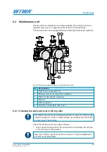
Page 39: ... screw for metering the oil addition 3 Slider for opening the containers 4 Oil tank 5 Water separator 6 Automatic condensate drain valve 6 3 1 Checking the lubricant level in the fog oiler The machine must only be commissioned if the oil reservoir of the fog oiler contains enough oil In case of high humidity use antifreeze for lubrication to avoid icing of the machine Check the lubricant level eve...

Page 40: ...ch the oil reservoir to the maintenance unit 6 3 2 Checking and adjusting the fog oiler 1 Let the machine run slowly under load 2 Check in the fog oiler inspection glass whether 1 drop of lubricant is fed after each 10 to 15 double strokes of the air motor 3 If this is not the case adjust the metering by turning the regulating screw on the fog oiler with a screwdriver 6 3 3 Checking and cleaning t...

Page 41: ...l Drain a small amount of release agent through the drain screw 2 1 2 1 2 Fig 30 Filling in 1 and draining 2 release agent for PROFIT Fig 31 Filling in 1 and draining 2 release agent for PHOENIX If the release agent is found to be contaminated with material residues you must assume that the packing of the material pump in question is worn In this case have the pump packing replaced as soon as poss...

Page 42: ...e filter element Different high pressure filters are used for the different AirCombi devices The machine card indicates which high pressure filter is used in your device Fig 32 Removing the filter element for high pressure filter type 01 1a 5 7 3 2a Fig 33 Removing the filter element for high pressure filter type 05 1b 5 7 3 2a 2b 7 4 5 6 1b 3 Fig 34 Removing the filter element for high pressure f...

Page 43: ...itted and retighten the nut 4 4 Check the O ring 7 replace if damaged 5 Screw the cap 3 on the high pressure filter and tighten it with the pin spanner 2b or the open end wrench 2a 6 5 3 Filter elements for high pressure filters Insert the filter element suitable for the spraying material and the spraying nozzle into the high pressure filter The mesh size should always be slightly finer than the b...

Page 44: ...ant acid free grease 0 4 kg 0000025 Lubricant for stainless steel 0000233 Plasticizer for filling the release agent vessel of the high pressure pump for the maintenance unit Substances required during maintenance and repair work see information in the spare parts lists The release agent and pneumatic oil are also available in larger containers on request 6 7 Special tools The following special too...

Page 45: ...ched The air pressure is too low or there is not enough air Increase the air pressure on the pneumatic regulator or check the air line for correct cross section Spraying nozzle new too big Install a smaller nozzle or use a bigger pump Spraying nozzle worn too big Install a new nozzle Air motor iced runs to slowly If possible reduce the air inlet pres sure Install a maintenance unit with oiler if o...

Page 46: ...e overflow Fluctuations in the spray jet Water in the atomizer air hose Retrofit water separator on the compressor Compressor too weak Choose stronger compressor to ensure enough air for pump and atomizer Gun filter blocked selected incor rectly defective or missing Check gun filter Observe operation instructions for spray gun Contaminated surface moist or contaminated atomizer air Retrofit water ...

Page 47: ...k place was determined in accordance with the DIN EN ISO 3744 DIN EN 31200 DIN EN 31201 and DIN 45635 20 standards Sound pressure level at 15 DH with 8 bar LP 84dB A Sound power level LW 95dB A 8 2 PHOENIX series Model 6530 11018 11032 Max free flow output l min 6 5 11 11 Pressure ratio 30 1 18 1 32 1 Pump capacity per double stroke cm 40 72 72 Max air inlet pressure bar 8 8 8 Max permissible oper...

Page 48: ...numbers and spare part numbers 8 4 Type plate The type plate is located on the cylin der of the material pump It contains the most important technical data for the high pressure pump Fig 36 Example of a type plate Please check that the data on the type plate is identical to the specifications on the machine card Please notify us immediately in case of discrepancies or if the type plate is missing ...

Page 49: ...Original operation manual AIRCOMBI 49 AirCombi_BAoDB_en_1701 rs ...

Page 50: ...7 0141 Fax 1 419 549 5173 Toll Free 1 855 757 0141 sales wiwa com www wiwausa com WIWA Subsidiary China WIWA Taicang Co Ltd Building A of Huaxin Industrial Park No 11 East Qingdao Road Taicang City Jiangsu Province 215400 P R China Tel 86 512 5354 8857 Fax 86 512 5354 8859 info wiwa china com www wiwa china com WIWA Middle East General Trading LLC Mohd Farhan Khan Jebel Ali Industrial 1 Dubai VAE ...

Reviews: