Subject to changes without notice !
Änderungen vorbehalten !
Gearless Lift Machine
WSG-25
Operating Instructions
EN
Code: GM.8.002673.EN
Date:
07. May 2019
Version: 0.13a
Page: 37
1
2
4
5
7
8
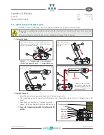
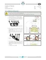
5. Insert the threaded rod (1) into the bearing block (8) and fasten
it using the nut (7).
Ensure that the nut (7) is completely screwed onto the threaded
rod (1) with 2-4 mm of thread left protruding beyond the nut.
The turning movement of the lever must not be obstructed.
6. Screw the nut (2) onto the threaded rod (1) flush with the slide
block (4).
The return motion device is now ready for use.
Information
f
As a rule, the threaded rod (1) may only be subjected to compressive load.
f
This causes the traction sheave to rotate anti-clockwise in the version shown above.
Anti-clockwise rotation of the traction sheave
Alternative position of the return motion device for clockwise
rotation of the traction sheave
Use of the return motion device
1
2
4
5
7
8
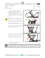
1. Once the return motion device has been installed correctly, the
brakes of the lift machine can be released.
2. Turn the nut (2) clockwise; the traction sheave will rotate anti-
clockwise.
Make sure that the nut (5) does not obstruct the movement of
the slide block (8).
3. If necessary, the slide block (4) can be repositioned by
inserting the threaded bolt (3) into a subsequent hole in the
traction sheave.
DANGER
f
When changing the position of the
threaded bolt in the holes, the lift must be
secured by its brakes.
DANGER
f
Make sure that you restore the lift system to its original state after completing the emergency evacuation. Take
particular care to remove the lever extensions and all parts of the mechanical return motion device.

