


Electrical installation
INTORQ | BA 14.0201 | 04/2016
20
5
Electrical installation
Important notes
5.1
Electrical connection
Ground/earth
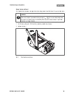
Use the PE screw in the terminal box (Figures 6 and 8) to establish the PE (earth) connection.
PE connection via the fixing screws on the motor is not permitted because there is no electrically conductive
connection between the brake and the guide sleeves!
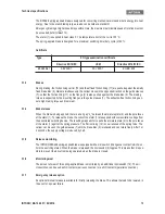
Temperature sensor connection (optional)
The spring-applied brake can be delivered with PTC sensors according to DIN 44082 for temperature mon-
itoring (reference temperature 130 °C). The signal is evaluated via a PTC thermistor tripping device provided
by the customer.
Connection: AWG 26 blue/blue
DANGER
There is a risk of injury by electrical shock!
❚
Electrical connection must only be carried out by skilled personnel!
❚
Only carry out connection work when no voltage is applied (no live parts)! There is a risk of
unintended start-ups or electric shock.
NOTICE
❚
It must be ensured that the supply voltage corresponds to the name plate data.
❚
Voltages must be adjusted to the local environment!
NOTICE
❚
If emergency switching off is carried out without the required suppressor circuit, the control
unit may be destroyed.
❚
Observe the correct polarity of the suppressor circuit!
Electrical installation
INTORQ | BA 14.0201 | 04/2016
21
5.2
Microswitch
5.2.1
Microswitch as NC contact (series connection)
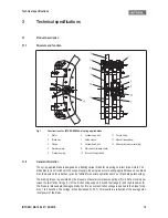
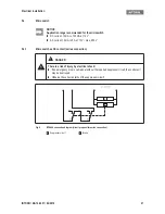
Fig. 5
BFK466 connection diagram (circuit proposal for series connection)
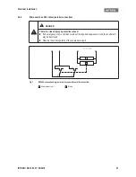
NOTICE
Application range recommended for the microswitch
❚
DC current: 10 mA to 100 mA at 12 V
❚
AC current: 10 mA to 5 A at 12 V / max. 250 V
DANGER
There is a risk of injury by electrical shock!
❚
If an emergency stop is carried out without the required suppressor circuit, the control unit
may be destroyed.
❚
Observe the correct polarity of the suppressor circuit!
AA
Suppressor circuit
B
Brake
A
B


