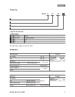
Technical specifications
INTORQ | BA 14.0201 | 04/2016
12
3
Technical specifications
3.1
Product description
3.1.1
Structure and function
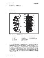
Fig. 1
Construction of an INTORQ BFK466-61 spring-applied brake
3.1.2
General information
The spring-applied brake is designed as a floating caliper brake for mounting on direct drive motors. The
brake disc (2) is not included in the scope of supply. By using two or more spring-applied brakes on one brake
disc, the demand for redundancy can be fulfilled for special applications such as lift and stage technology.
The braking torque is generated by the pressure of several compression springs (5) via friction locking be-
tween the two friction linings (11) of the friction lining support (12) and the flange (3) and the brake disc (2).
The brake is released electromagnetically. For this, an overexcitation voltage is applied to the brake for ap-
prox. 1 to 2 seconds. The voltage is then decreased by 50 %. This results in a reduction of the average elec-
trical power of the brake.
1
Stator
6
Cylinder head bolt
11 Friction lining
2
Brake disc
7
Guide sleeve
13 Manual release lever
3
Flange
8
Cylinder head bolt
14 Microswitch (wear monitoring)
4
Armature plate
9
Microswitch (release check)
5
Pressure spring
10 Terminal box (optional)
Technical specifications
INTORQ | BA 14.0201 | 04/2016
13
The BFK466 spring-applied brake is designed for converting mechanical work and kinetic energy into heat
energy. Due to the static braking torque, loads can be held at a standstill.
Emergency braking at higher speeds is possible. Here, the maximum permissible speed of rotation must not
be exceeded (refer to
14).
The stator (1) is supplied in heat class F. The temperature limit of the coil is 155 °C.
The spring-applied brake is designed for a maximum switching time (duty cycle) of 80 %.
Certificate
3.1.3
Brakes
During braking, the friction lining carrier (12) and the affixed friction lining (11) are pushed against the axially
fixed brake disc (2). Almost simultaneously, the caliper moves in the opposite direction on the guide sleeves
(7), so that the friction lining (11) on the flange (3) is also pushed against the brake disc (2). The braking
torque is supported by the mounting flange via the guide sleeves (7). The asbestos-free friction linings en-
sure high braking torque and low wear.
3.1.4
Brake release
When the brake is being applied, there is an air gap “s
L
" between the armature plate (4) and the pole faces
of the stator (1). To release the brake, the coils of the stator (1) are supplied with overexcitation voltage from
the associated switching device. The resulting magnetic force pulls the armature plate (4) to the pole faces
of the stator (1) against the spring pressure. The friction lining (12) is now relieved of the spring force. The
caliper can move on the guide sleeves (7) until the brake disc (2) is relieved and can rotate freely. After 1 or
2 seconds, the supply voltage is reduced by half.
3.1.5
Release monitoring
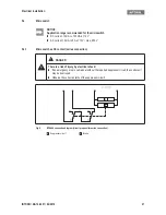
The INTORQ BFK466 spring-applied brake is equipped with a microswitch (changeover contact) which mon-
itors the switching status. When the brake is released, the microswitch (9) toggles. This means that it is pos-
sible to prevent the drive from being operated when the brake is closed.
3.1.6
Monitoring wear
The amount of wear of this spring-applied brake is monitored by an additional microswitch (14). The mi-
croswitches can be used as NC contacts (series connection) or as NO contacts (parallel connection).
3.1.7
Emergency release option
An optional manual release is available for briefly releasing the brake. This allows the load to be lowered in
the event of a power failure.
Type
EC-type examination certificate
Directive 95/16/EC
UCM
Directive 2014/33/EC
BFK466-61
ABV 908/1
ESV 908/1
EU-BD 908


