Installation
ProCam 1500 SFI Manual
7
Ch 2
1095900
10. Look at TB103. There may be a plastic plug over pin 5 on this terminal block. If
so, remove the pin using needle-nose pliers. Plug the 10-pin connector into TB103.
11. You are finished installing ProCam 1500 SFI. Re-connect the ProCam 1500
panel to your enclosure and re-tighten the hardware. Turn power back ON to
both ProCam 1500 and to your feed.
12. Check that ProCam 1500 is operating normally. If it is working properly, you
are now ready to use SFI. Go to the next chapter to learn how to set up and
operate your feed through ProCam 1500. If the unit powers up with a garbled
display or "rolling" LEDs, turn the power OFF and recheck how you installed
your firmware. Review "Installing SFI firmware" earlier in this chapter. If the
unit is still malfunctioning and you cannot find the reason for the problem, call
Data Instruments technical advisors for assistance.
10
9
8
7
6
5
4
3
2
1
-CLK
+CLK
-DATA
+DATA
GND
TXD OUT (RS232)
-RXD
+RXD
-TXD
+TXD
1
2
3
4
5
6
7
TXD
GND
RXD
SHIELD
2
3
7
brown
shield
white
Remove jumper
at brown wire
J2
DB-25 keypad
display board
terminal block
inside feed control
cabinet
black
CWP SM Feed Controller
ProCam 1500
TB103
Serial port on CWP SM
Feed Controller
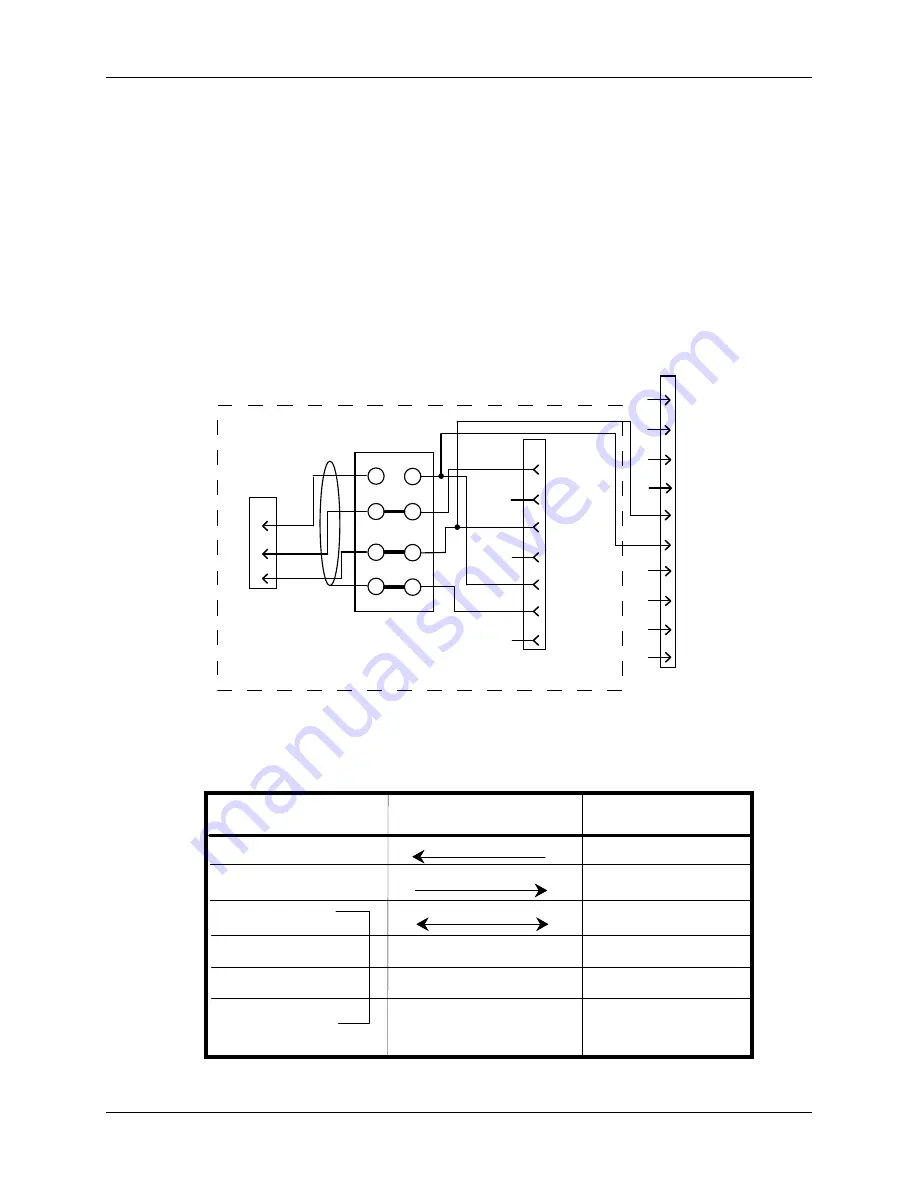
Figure 2-3. CWP SM wiring connections
Table 2-1A.
Wiring connections for Reliance Cut-To-Length (CTL)
feed controller
Red
Green
White
Wire & direction
of data flow
requires special 7-
pin connector
(supplied by PA)
#1 TXD
#5 RXD
#3 Ground
Reliance CTL
Feed RS-232
ProCam 1500
TB103
#6 Ground
Shield
(no connection)
(no connection)
Black
#7 +5Vdc
#4 -RXD
#5 TXD OUT
#6 GROUND
#3 +RXD


