background image

7

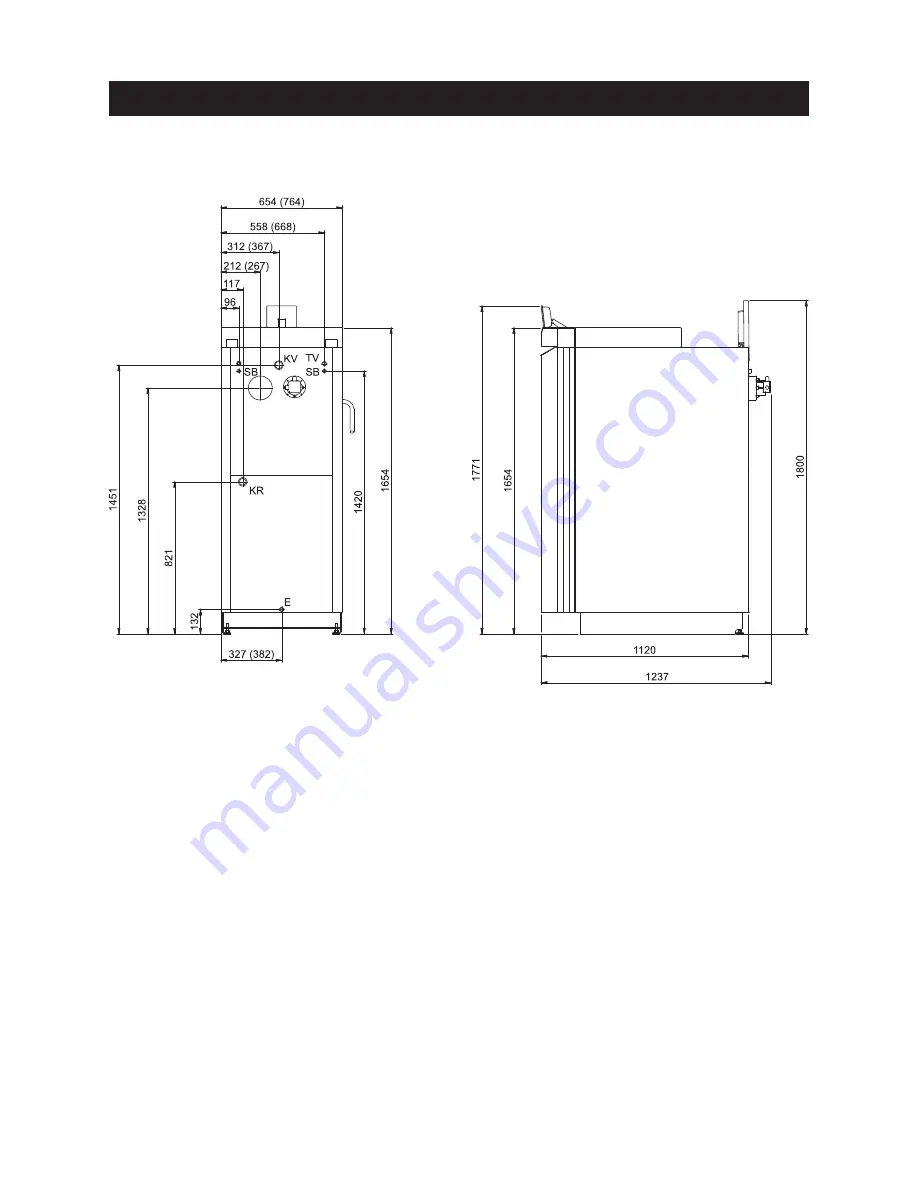
2.3 Dimensional sketches

Fig. 5

Rear view

Fig. 6

Left view

KV . . . . .Boiler feed (5/4” pipe)
KR . . . . .Boiler return (5/4” pipe)

TV . . . . .Thermal valve sensor (1/2” sleeve)

SB . . . . .Thermal safety device (1/2” tube)

E . . . . .Discharge 

For the Installer

2)

All dimensions in mm:

Details provided in brackets apply to 
LPW 360 and 500.

2) with cleaning cover open

Summary of Contents for LogWIN LWP 180

Page 1: ...Assembly instructions 08 2008 xxxxxx 00 LogWIN Wood gasification boiler...

Page 2: ...7 Installing the thermal process safeguard 20 2 8 Storing the instruction booklets 21 2 9 Initial start up and operating instructions 21 For the Electrician 22 3 1 Electrical connections 22 For the Se...

Page 3: ...function of or damage to the boiler or heating sys tem The specified safety requirements are to be followed in accordance with nationally applicable regula tions standards and guidelines 1 3 Flue A pr...

Page 4: ...vacuum cleaner magnetic flashlight gloves and apron Fig 2 LogWIN boiler 180 500 Fig 3 Cladding and control panel in 4 cardboard boxes In the filling chamber Instruction booklets Screws and small part...

Page 5: ...kg by removing parts which are easy to disassemble e g doors hook in plates burnthrough plates heating surface cleaning etc 2 2 2 Installing in the boiler room installation room The boiler can be ins...

Page 6: ...ation guidelines for boiler room installation room 494 604 min 580 680 min 180 min 650 760 min 360 400 min 500 600 654 764 1120 1 Recommended minimum room heights 1950 mm All measurements in mm Detail...

Page 7: ...ew KV Boiler feed 5 4 pipe KR Boiler return 5 4 pipe TV Thermal valve sensor 1 2 sleeve SB Thermal safety device 1 2 tube E Discharge For the Installer 2 All dimensions in mm Details provided in brack...

Page 8: ...s essential for correct operation of a wood fired heating system The fuel must always be selected and the heat load of the building calculated Heating characteristics e g bringing the hot water tank u...

Page 9: ...ns of accumulator tank CWK CWK or CWK CWP The accumulator tanks can be combined with one another in parallel in a flexible way The connection set CW 021 accessory can be used for the following tank co...

Page 10: ...of the return flow must be increased using a mixing pump or valve In order to achieve good temperature stratification in the accumulator tank we recommend setting the boiler circuit to a 15 20 K diff...

Page 11: ...sult measures must be taken to dissipate the surplus energy see section 2 4 4 Heating circuits Minimum heat con sumption 2 4 7 Thermal safety device heat exchanger The thermal safety device is used fo...

Page 12: ...r LWP 360 500 only 10 Top insulation 11 Insulation flue outlet 12 Retaining bracket for blower plug 13 Rear wall top 14 Rear wall bottom 15 Air control 16 Lever for cleaning heating sur faces 17 Hange...

Page 13: ...e same colour Fig 13 Fastening clips with yellow mark Fig 11 Installing the thermocontrol sensor For the Installer Fig 10 Threading through thermocontrol sensor Thread thermocontrol sensor green cable...

Page 14: ...with control panel in four places Fig 16 Hooking in side panels at the bot tom Fig 18 Screwing down LogWIN 360 500 side walls with connecting bracket in two places Fig 15 Sliding connecting bracket un...

Page 15: ...and flue gas temperature sensor towards the rear from the control panel in the cable duct on the flue tube side Insert boiler sensor and safety temperature limiter sensor as far as possible into the i...

Page 16: ...ash doors with 4TT self tapping screws Fig 21 Depending on accessibility either fit lever for cleaning heating surfaces on the left or right side Punch through the cut out insert lever through opening...

Page 17: ...front bottom top using 4TT self tapping screws Fig 27 Thread cable for Info WIN from the control panel sideways through the opening in the side wall and cladding door Fig 28 Cable protection must be...

Page 18: ...ng cladding door switch Secure cladding door switch in cladding door switch cover with 2 screws Fig 33 Screw cladding door switch cover on side walls 2 x and control panel 2 x Fig 34 When closing the...

Page 19: ...llation room Keep ash pan under boiler For the Installer Fig 36 Hinging in boiler cover Fig 37 Securing boiler cover in 2 places Fig 38 Putting on the rear boiler cover Fig 39 Fitting hanger ash pan u...

Page 20: ...Install the exhaust pipe upward to the flue 45 is the ideal angle Maximum exhaust pipe length to flue 3 m b Avoid 90 bends 45 bends are better c Do not push the exhaust pipe too far into the flue d Do...

Page 21: ...Do not heat up first Start up and maintenance are part of the guarantee requirements of the war ranty conditions The following preconditions must be met before you order the initial start up 1 Boiler...

Page 22: ...ents may only be performed by a qualified technician The regulations and spec ifications of VE VDE SEV and local ordinances must be followed We recommend using fine wire PVC sheathed cables e g H05VV...

Page 23: ...rol panel and should be connected with fine wire PVC sheathed cables Fig 46 Fig 45 Loosening 1 screw at top and removing the control panel cover For the Electrician Fig 43 Loosening 2 screws at front...

Page 24: ...le for cleaning Fig 49 Connecting plugs rear view Fig 52 Putting on the rear boiler cover Power plug Fig 47 Hinging in control panel cover Fig 50 Hinging in boiler cover Fig 48 Securing control panel...

Page 25: ...te There is no need to remove the fitting for this pur pose Fig 55 Thermal process safeguard 4 2 Checking and servicing the thermal process safeguard Please inform your customer For the Service Techni...

Page 26: ...0 x 1520 Filling door dimensions W x H mm 430 x 397 Filling chamber depth mm 562 Electrical power consumption W 47 53 58 60 66 Values from type test with beech Testing office T V S D Munich test repor...

Page 27: ...odifications on the Service level Service level Reserved for trained service personnel only Menu automatic detection normal Embers maintenance Burnout Language Deutsch English Fran aise Italiano Caste...

Page 28: ...longer than 5 seconds Fig 60 The menu item or sub menu item is exited by pressing the Back button or after a delay of 45 seconds Use the arrow buttons to select the Values Restart temperature or Actua...

Page 29: ...es back on and the boil er resumes normal heating operation Factory setting 75 C Possible settings 65 C or 75 C Fig 65 Temp Boiler 68 C Temp chamb 578 C Fan speed 2150 rpm Pos Prim airfl 60 Pos Sec ai...

Page 30: ...st Induced draught fan Primary airflap Secondary airflap O2 heating 4 5 6 Installation of MES modules Display if an MES module is installed connected or uninstalled disconnect ed Fig 69 Fig 68 Fig 69...

Page 31: ...31 For the Service Technician 4 6 LogWIN basic circuitry 092147 02...

Page 32: ...0 1 865 13 81 Fax 43 0 1 865 13 81 E mail kundendienst at windhager com Technical assistance Tel 43 0 62 12 23 41 238 Fax 43 0 62 12 23 41 259 Headquarters Windhager Zentralheizung GmbH A 5201 Seekirc...

Reviews: