background image

Page 12

15628-0-0903

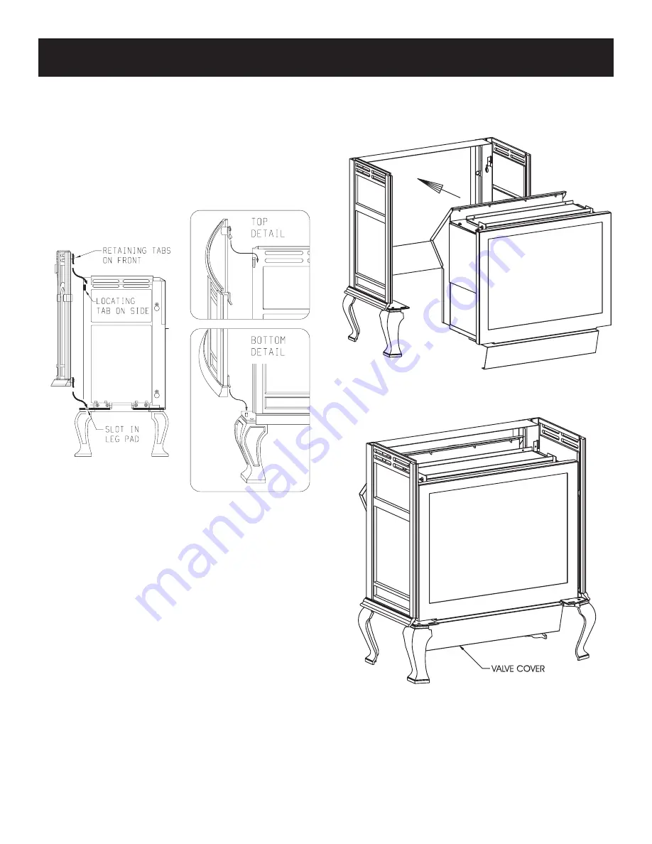
11. Refer to Figure 10, attach casting front to casting by using the

(4) retaining tabs on the casting front. The (2) top, retaining
tabs on the casting front will be placed behind the (2) top,
locator tabs on the front of the casting sides. The (2) bottom,
retaining tabs will be inserted into the (2) 9/16" slots on the
front, leg pads. Place the top, retaining tabs behind the top,
locator tabs as you pivot inward the bottom of the casting
front in order to insert the bottom, retaining tabs into the
slots.

Figure 10

12. The following procedure will provide a snug fit between the

casting front and the casting sides. Grasp the right, front leg,
push inward on the leg in order to provide a snug fit between
the casting front and the casting side. Continue to hold the
right, front leg as you completely tighten the (2) 3/8" bolts that
attach the leg pad to the right,  casting side. Repeat procedure
for left, front leg to achieve a snug fit between the casting front
and the casting side.

13. Remove the casting front from the casting.
14. Refer to Figures 11 and 12, the appliance firebox can now be

inserted into the casting. Center the firebox in the casting.
Attention: Remove (1) Phillips-head screw in the top of the
valve cover. The screw is used to secure the valve cover in
place during shipping. The (1) Phillips-head screw can be
discarded.

15. Refer to Figure 13, align (2) slotted clearance holes on upper

mounting brackets with (2) screw holes on rear cover. Align
(2) slotted clearance holes on casing support with (2) screw
holes at bottom of air drop assembly. Attach firebox to rear
cover and casing support with (4) 10 x 1/2" screws.

16. Attach casting front to outer casting as described in Step 11.
17. Place the casting top onto the outer casting. The casting top

nests into the outer casting.

18. Insert center grill, left grill and right grill into casting top.

Figure 11

Figure 12

19. Level appliance by adjusting leveling bolts.
20. Assembly of stove casting is completed.

ASSEMBLY OF STOVE CASTING (continued)

Summary of Contents for Classic CIDV-30-20

Page 1: ...sult a qualified installer service agency or the gas supplier AVERTISSEMENT Une installation un réglage unemodification unentretienouunemaintenance incorrects peuvent entraîner des dommages matériels deslésionscorporellesoulapertedevies humaines Consulter le manuel des usagers fourn avec ce générateur d air chaud AVERTISSEMENT Quiconque ne respecte pas à la lettre les instructions dans le présent ...

Page 2: ...te Installation 16 Termination Clearances 17 Vent Clearances 18 Vent System Identification 19 Framing and Finishing 20 21 Horizontal Termination 21 Vertical Termination 22 23 Log Placement 23 Operating Guidelines 24 Lighting Instructions 25 Pilot Flame Characteristics 26 Main Burner Flame Characteristics 26 27 Wiring 27 28 Maintenance 29 30 Troubleshooting 31 How To Order Repair Parts 32 Parts Lis...

Page 3: ...keep the appliance area clear and free from com bustible material gasoline and other flammable va pors and liquids DO examine venting system periodically and replace damaged parts CAUTION The glass used in your heater is a special high temperature ceramic glass If the glass is cracked or damaged in any way it should be replaced only with a complete glass frame assembly from Empire See parts list o...

Page 4: ...m service or make adjustments in an area where the conditions are such that you may not detect the odor if there has been a leak of LP Gas Odor fade due to oxidation by rust or adsorption on walls of new cylinders and tanks is possible Therefore people should be particularly alert and careful when new tanks or cylinders are placed in service Odor fade can occur in new tanks or reinstalled old tank...

Page 5: ...t 42nd St New York NY 10036 Installer l appareil selon les codes ou règlements locaux ou en l absence de tels règlements selon les Codes d installation CAN CGA B149 This model is a direct vent gas appliance and is designed to operate with all combustion air being siphoned from the outside of the building and all exhaust gases expelled to the outside of the building Warning This unit is not for use...

Page 6: ... Green CIPS 1 Porcelain Sand CIPN 1 Porcelain Navy CIPR 1 Porcelain Red Accessories GWSG T 750 Millivolt Wall Thermostat TMV Millivolt Wall Thermostat Reed Switch DVKH 1 Direct Vent Kit for Horizontal Run Includes DVKA 1 Adapter DVKV 1 Direct Vent Kit for Vertical Run Includes DVKA 1 Adapter DVKA 1 Direct Vent Kit Adapter FRBC 1 Battery Operated Remote Control FRBTC 1 Battery Operated Remote Contr...

Page 7: ...liance connected control valve will sustain damage NOTE The gas control is equipped with a captured screw type pressure test point therefore it is not necessary to provide a 1 8 test point up stream of the control A gas valve and ground joint union should be installed in the gas line upstream of the gas control to aid in servicing It is required by the National Fuel Gas Code that a drip line be in...

Page 8: ...g 36 inches Rear Wall 2 inches Side Wall 6 inches Heater Corners 45 angle to Wall 4 inches Floor 0 inches Installation on Rugs and Tile If this appliance is to be installed directly on carpeting tile or other combustible material other than wood flooring the appli ance shall be installed on a metal or wood panel extending the full width and depth of the appliance The base referred to above does no...

Page 9: ...lied 1 4 20 x 1 Phillips Head Bolt R 3188 4 1 4 20 x 3 8 Phillips Head Bolt R 3646 16 1 4 20 x 1 2 Leveling Bolt R 3747 4 No 10 x 1 2 R 2737 16 Hex Washer Head Screw 1 4 20 Washer Head Nut R 3185 4 Leg Pad A see Figure 7 CI 008 2 Leg Pad B see Figure 7 CI 009 2 1 1 4 x 1 2 Retaining Tab CI 007 4 see Figure 9 1 4 x 9 32 Washer Not Shown R 1150 8 ...

Page 10: ...ns Follow 3 RefertoFigure7 thelegpadswillhavetheletter A and B stamped into the metal Place leg pad A and leg pad B at the bottom of each casting side Leg pad A attaches to the front of the casting side right and to the rear of the casting side left Leg pad B attaches to the rear of the casting side right and to the front of the casting side left Position the 3 4 flange on the leg pad against the ...

Page 11: ...Position the completed portion of the casting in the approximate location for installation as the completed assembly will be heavy 9 Refer to Figure 9 remove protective packing foam from casting front and window Remove the 1 3 4 bolt and 1 1 4 washer from top of window Remove 1 3 8 bolt and 1 5 8 x 3 4 retaining tab from bottom of window Remove the window from casting front Remove the protective s...

Page 12: ...rleft frontlegtoachieveasnugfitbetweenthecastingfront and the casting side 13 Remove the casting front from the casting 14 Refer to Figures 11 and 12 the appliance firebox can now be inserted into the casting Center the firebox in the casting Attention Remove 1 Phillips head screw in the top of the valve cover The screw is used to secure the valve cover in place during shipping The 1 Phillips head...

Page 13: ... 5 Placethecastingtopontothecasting Thecastingtopnestsinto the casting 6 Insert center stone inlay left stone inlay and right stone inlay into casting top 7 Installation of stone inlay is completed Stone Inlay Hardware Package Parts List Part Part Quantity Description Number Supplied 11 5 8 x 11 5 8 Top Shield CI 091 1 3 8 Bolt R 3646 1 WIRE CHANNEL INSTALLATION The ON OFF REMOTE switch with harne...

Page 14: ... cotter pin must remain flat The tip of the cotter pin must never be bent over If the tip of the cotter pin is bent over it could prevent the delayed ignition reset switch from functioning during a delayed ignition 6 Replacement of cotter pin into delayed ignition reset switch assembly is completed Reassembly and Resealing Gas Accumulation Relief System Relief Doors and Combustion Chamber Whenever...

Page 15: ...et Maximum horizontal run from appliance outlet 12 feet 3 66m Maximumverticalriseandhorizontalrunisacombinedtotalof25 feet 7 62m Maximum elbows 2 90 for the second elbow subtract 5 feet from a horizontal run To Use the Vent Graph EXAMPLE A If the vertical rise from the appliance outlet is 21 feet the horizontalruntotheouterwallflangeoftheventterminationmust not exceed 4 feet with 1 90 elbow EXAMPL...

Page 16: ... vertical vent installation The restrictor plate can be used when the vertical vent rise is between 10 feet and 25 feet In a vertical vent rise the rear yellow flame on the main burner can be reduced due to the drawing action from the flue exhaust pipe and the air inlet pipe A decrease in the height or the appearance of the yellow flame may occur when the vertical vent rise is between 10 feet and ...

Page 17: ...rmation on Various Venting Routes and Components Important It is always best to locate the appliance in such a way that minimizes the number of offsets and horizontal vent length Figure 20 Since it is very important that the venting system maintain its balance between the combustion air intake and the flue gas exhaust certain limitations as to vent configurations apply and must be strictly adhered...

Page 18: ...ine of the regulator I clearance to service regulator vent outlet 6 feet 1 8m minimum J clearance to non mechanical air supply inlet to building or the combustion air inlet to any other appliance 12 inches 30cm minimum for appliances 100 000 Btuh 30 kW 36 inches 90cm minimum for appliances 100 000 Btuh 30kW K clearance to a mechanical air supply inlet 6 feet 1 8m minimum L clearance above paved si...

Page 19: ...efirstcomponent a straight pipe on the top of the appliance or rotate the vent elbow to the horizontal positon then add horizontal and vertical pipe lengths and then a horizontal or vertical termination kit Elbows can be added where neccessary See Pages 15 and 16 for venting requirements Allventsystemcomponentslockintoplacebyslidingtheconcentric pipe section with four 4 equally spaced interior bea...

Page 20: ...rough which the vent passes Position the firestops on both sides of the 10 inch x 10 inch hole previously cut Secure with nails or screws Continue the vent run through the firestops See Figure 25 Figure 25 Vertical runs of this system which pass through ceilings require the use of ONE 1 ceiling firestop at the hole in each ceiling through which the vent passes Position a plumb bob directly over th...

Page 21: ...he termination cap with the four wood screws provided Before attachment of the termination run a bead of silicone sealant rated above 250 F on its outside edge too so as to make a seal to that exterior wall NOTE Woodscrewscanandshouldbereplacedwithappropriate fastenersforuseonstucco brick concreteorothertypes of siding CAUTION If exterior walls are finished with vinyl siding it is necessary to ins...

Page 22: ...n the vent Remove any bird nests or other foreign material 3 Check for evidence of excessive condensate such as water droplets forming in the inner liner and subsequently dripping outatjoints Continuecondensatecancausecorrosionofcaps pipe and fittings It may be caused by having excessive lateral runs too many elbows and exterior portions of the system being exposed to cold weather 4 Inspect joints...

Page 23: ...round 6 5 8 inch diameter pipe and nailed in place to framing members There MUST BE a 2 inch clearance to combustibles above 6 5 8 inch diameter pipe and elbows and 1 inch clearance on both sides and bottom of 6 5 8 inch to combustibles on all horizontal pipe sections and elbows Vertical runs of this vent systems must be supported every 4 feet above the appliance flue outlet by wall brackets attac...

Page 24: ...ll not require such purging if the gas valve is not turned to OFF Standing Pilot Operation 1 Follow the SAFETY and LIGHTING INSTRUCTIONS for standing pilot controls found in this manual and on labels found attached to the appliance CAUTION During the initial purging and subsequent lightings never allow the gas valve control knob to remain depressed in the pilot position without pushing the piezo i...

Page 25: ...setting 2 Turn off all electric power to appliance if service is to be performed if applicable 3 Lower valve cover 4 Push in gas control knob slightly and turn clock wise to OFF Do not force 5 Raise valve cover TO TURN OFF GAS TO APPLIANCE LIGHTING INSTRUCTIONS 1 STOP Read the safety information above 2 Set the thermostat to lowest setting 3 Turn off all electric power to the appliance if appli ca...

Page 26: ...ER FLAME CHARACTERISTICS Figure 37 shows a correct main burner flame pattern Figure 38 shows an incorrect main burner flame pattern Air Shutter Adjustment An air shutter adjusting screw is located on the exterior bottom of the inner body Screw air shutter adjusting screw IN to close air shutter top increase yellow flame Screw air shutter adjusting screw OUT to open air shutter top decrease yellow ...

Page 27: ...d bare are not used Operation of ON OFF REMOTE Switch with Accessories 750 Millivolt Wall Thermostat GWSG T Connect the green and red stripped and bare wires on the ON OFF REMOTE switch wire harness to the wall thermostat Turn the ON OFF REMOTE switch on the wire channel to the REMOTE position Set the wall thermostat to the desired temperature It is important to use wire of a gauge proper for the ...

Page 28: ...must turn the appliance ON or OFF with appropriate accessory Wall Thermostat Operation 1 Turn the ON OFF REMOTE switch on wire channel to REMOTE position 2 Turn accessory FRBC 1 FREC 1 or FWS 1 OFF 3 Turn wall thermostat ON and set appropriate temperature Wall thermostat will cycle the appliance ON and OFF Installation of Remote Receiver Figure 39 1 Attach from left to right the slide on cover pla...

Page 29: ...tances should this appliance be operated withouttheglassfrontorwithabrokenglassfront Replacement of the glass with gasket as supplied by the manufacturer should be done by a qualified service person 4 Do not abuse the glass by striking or hitting the glass WARNING Do not use abrasive cleaners on glass Do not attempt to clean glass when glass is hot Failure to follow these warnings could cause a se...

Page 30: ...e a year MAINTENANCE continued Cleaning Procedure 1 Let the unit cool if it has been operating 2 Shut off gas supply 3 Lower valve cover on firebox 4 Release two door latches at bottom of firebox 5 Grasp bottom of glass frame lift glass frame upward in order to release glass frame from lip on top of firebox 6 Vacuum burner compartment especially around orifice primary air openings 7 Align and plac...

Page 31: ...the pilot position with the pilot lit and the ON OFF switch in the OFF position Replace the faulty thermopile if the reading is below the specified minimum With the pilot in the ON position disconnect the thermopile leads from the valve Take a reading at the thermopile leads The reading should be 325 millivolts minimum Replace the thermopile if the reading is below the minimum c Defective valve Tu...

Page 32: ...30 M 163 FLUE CONNECTOR TUBE GASKETS 31 15612 AIR DROP ASSEMBLY 32 M 160 VENT ELBOW GASKET 33 R 7221 FRONT LOG 34 R 7220 REAR LOG 35 R 7222 TOP LOG 36 15609 GLASS ASSEMBLY 37 15502 GLASS FRAME 38 R 3436 ON OFF REMOTE SWITCH 39 CI 331 CHANNEL DIVIDER 40 CI 329 WIRE CHANNEL 41 15501 CASING SUPPORT 42 15497 REAR COVER NS R 7294 WIRE ASSEMBLY NS CI 253 MAGNET ASSEMBLY NS 15610 TUBING VALVE TO PILOT NS...

Page 33: ...Page 33 15628 0 0903 19 29 30 PARTS VIEW FOR CIDV 30 20 ...

Page 34: ... NAVY ENAMEL 6 R 3944 TOP BLACK PAINT 6 R 3683 TOP BLACK ENAMEL 6 R 3691 TOP SAND ENAMEL 6 R 3699 TOP GREEN ENAMEL 6 R 3707 TOP RED ENAMEL 6 R 3715 TOP NAVY ENAMEL 7 CI 007 RETAINING TAB 4 REQUIRED 8 R 3946 SIDE RIGHT BLACK PAINT 8 R 3685 SIDE RIGHT BLACK ENAMEL 8 R 3693 SIDE RIGHT SAND ENAMEL 8 R 3701 SIDE RIGHT GREEN ENAMEL 8 R 3709 SIDE RIGHT RED ENAMEL 8 R 3717 SIDE RIGHT NAVY ENAMEL 9 R 3947 ...

Page 35: ...Page 35 15628 0 0903 PARTS VIEW FOR STOVE CASTING Models CIFB 1 CIPB 1 CIPG 1 CIPS 1 CIPN 1 CIPR 1 ...

Page 36: ... 2 screws provided in hardware package 8 Route fan control wires through 1 2 extruded hole on channel divider Attach fan control wires to fan control 9 Attach channel divider with 2 10 x 1 2 screws from Step 5 10 RoutewiresfromfancontrolandON OFF REMOTEswitch within wire channel 11 Attach wire channel to channel divider with 2 10 x 1 2 screws from Step 4 Refer to Wire Channel Installation Page 13 ...

Page 37: ... absence of local codes with the National Electrical Code ANSI NFPA 70 or Canadian Electrical Code CSA C22 1 if an external electrical source is utilized This appliance is equipped with a three prong grounding plug for your protection against shock hazard and should be plugged directly into a properly grounded three prong receptacle Do not cut or remove the grounding prong from this plug For an un...

Page 38: ...Page 38 15628 0 0903 SERVICE NOTES ...

Page 39: ...Page 39 15628 0 0903 SERVICE NOTES ...

Page 40: ...3 Empire Comfort Systems Inc Nine Eighteen Freeburg Ave Belleville Illinois 62222 0529 PH 1 800 851 3153 PH 1 618 233 7420 FAX 1 800 443 8648 FAX 1 618 233 7097 E MAIL info empirecomfort com WEB SITE www empirecomfort com ...

Reviews: