


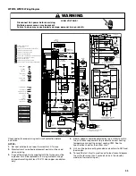

27
SEQUENCE OF OPERATION
Power Up
The normal power up sequence is as follows:
■
115 VAC power applied to furnace.
■
Integrated control module performs internal checks.
■
Integrated control module LED will light.
■
Integrated control module monitors safety circuits
continuously.
■
Furnace awaits call from thermostat.
Heating Mode—Mode DIP Switch Set to
1 STG Position
The normal operational sequence in heating mode is as follows:
■
R and W thermostat contacts close, initiating a call for heat.
■
Integrated control module performs safety circuit checks.
■
Induced draft blower is energized for a 15-second prepurge
period causing the pressure switch contacts to close.
■
Igniter warm-up begins after 15-second prepurge expires.
■
Low-stage and high-stage gas control valves open at the end
of the igniter warm-up period, delivering gas to the burners
and establishing flame.
■
Integrated control module monitors flame presence. Gas
control valve will remain open only if flame is detected.
■
Circulator blower is energized on high heat speed following a
fixed 30-second blower on delay. Electronic air cleaner
terminals are energized with circulator blower.
■
Furnace operates; integrated control module monitors safety
circuits continuously.
■
R and W thermostat contacts open, completing the call for
heat.
■
Gas control valve closes, extinguishing flame.
■
Induced draft blower is de-energized following a 15-second
post-purge period.
■
The circulator blower remains at high-heat speed for the
selected heat off delay period.
■
Furnace awaits next call from thermostat.
Heating Mode—Mode DIP Switch Set to
2 STG Position
The normal operational sequence in heating mode is as follows:
■
R and W thermostat contacts close, initiating a call for heat.
■
Integrated control module performs safety circuit checks.
■
Induced draft blower is energized for a 15-second prepurge
period causing the pressure switch contacts to close.
■
Igniter warm-up begins after 15-second prepurge expires.
■
Low-stage and high-stage gas control valves open at the end
of the igniter warm-up period, delivering gas to the burners
and establishing flame.
■
High-stage gas control valve closes after 5 seconds;
low-stage gas control valve remains open.
■
Integrated control module monitors flame presence. Gas
control valve will remain open only if flame is detected.
■
Circulator blower is energized on low-heat speed following a
fixed 30-second blower on delay. Electronic air cleaner
terminals are energized with circulator blower.
■
Furnace is now operating in low-stage heating mode.
■
Furnace operates; integrated control module monitors safety
circuits continuously.
■
If low-stage delay period expires, control will shift operation
from low-stage heating mode operation to high-stage heating
mode operation. Control will energize circulator blower
high-heat speed and high-stage gas control valve.
■
Furnace is now operating in high-stage heating mode.
■
R and W thermostat contacts open, completing the call for
heat.
■
Induced draft blower is de-energized following a 15-second
post-purge period.
■
Circulator blower is de-energized following a heat off delay
period (selectable 100 to 150 seconds; factory-set at
150 seconds).
If the furnace is operating in the low-stage heating mode
when thermostat contacts open, circulator remains at
low-heat speed for the selected delay off period. If the
furnace is operating in high-stage heating mode when the
thermostat contacts open, the circulator blower remains at
high-heat speed for the selected heat off delay period.
■
Furnace awaits the next call from thermostat.
Cooling Mode
The normal operational sequence in cooling mode is as follows:
■
R and Y thermostat contacts close, initiating a call for cool.
■
Integrated control module performs safety circuit checks.
■
Outdoor fan and compressor are energized.
■
Circulator blower is energized on cool speed following a fixed
5-second on delay. Electronic air cleaner terminals are
energized with circulator blower.
■
Furnace circulator blower and outdoor cooling unit run;
integrated control module monitors safety circuits
continuously.
■
R and Y thermostat contacts open, completing the call for
cool.
■
Outdoor fan and compressor are de-energized.
■
Circulator blower is de-energized following a fixed 45-second
cool off delay period. Electronic air cleaner terminals are
de-energized.
■
Furnace awaits the next call from thermostat.
Fan Only Mode
The normal operational sequence in fan only mode is as follows:
■
R and G thermostat contacts close, initiating a call for fan.
■
Integrated control module performs safety circuit checks.
■
Circulator blower is energized on low-heat speed. Electronic
air cleaner terminals are energized.
■
Circulator blower runs; integrated control module monitors
safety circuits continuously.
■
R and G thermostat contacts open, completing the call for
fan.
■
Circulator blower is de-energized. Electronic air cleaner
terminals are de-energized.
■
Furnace awaits the next call from thermostat.


