


22
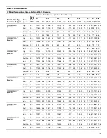
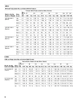
Data in accordance with NFPA pamphlet Number 54.
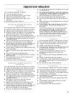
Start-Up Procedure and Adjustment
■
Furnace must have a 115VAC power supply properly
connected and grounded. Proper polarity must be maintained
for correct operation.
■
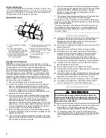
An interlock switch prevents furnace operation if the blower
door is not in place. Keep the blower access door in place
except for inspection and maintenance.
■
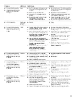
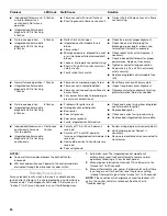
This furnace is also equipped with a self-diagnosing
electronic control module. In the event a furnace component
is not operating properly, the control module LED will flash on
and off in a factory-programmed sequence, depending on the
problem encountered. This light can be viewed through the
observation window in the blower access door. See
“Troubleshooting” for further explanation of the lighting
codes.
■
Follow the start-up and adjustment items. See “Operational
Checks.”
Furnace Operation
■
Purge gas lines of air prior to start-up.
NOTE: Do not purge lines into an enclosed burner
compartment.
■
Check for leaks using an approved chloride-free soap and
water solution, an electronic combustible gas detector or
other approved method.
■
Verify that all required kits (propane gas, high altitude, etc.)
have been appropriately installed.
■
An interlock switch prevents furnace operation if the blower
door is not in place. Keep the blower access doors in place
except for inspection and maintenance.
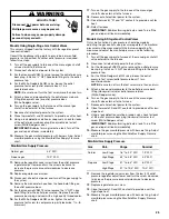
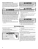
Furnace Start-Up
1. Close the manual gas shutoff valve external to the furnace.
2. Disconnect the electrical power to the furnace.
3. Set the room thermostat to the lowest possible setting.
4. Remove the burner compartment door.
NOTE: This furnace is equipped with an ignition device which
automatically lights the burner. Do not try to light the burner by
hand.
5. Push the switch to the OFF position.
6. Wait 5 minutes to clear out any gas. Check for a gas odor,
including near the floor.
7. If a gas odor is detected following the 5-minute waiting
period, immediately leave the building and call your gas
supplier or the fire department.
8. If no gas odor is detected after 5 minutes, push the switch to
the ON position.
9. Replace the door on the front of the furnace.
10. Open the manual gas shutoff valve external to the furnace.
11. Reconnect the electrical power supply to the furnace.
12. Set the room thermostat to the desired temperature.
NOTE: There is an approximate 30-second delay between
thermostat energizing and burner firing.
Furnace Shutdown
1. Set the thermostat to lowest setting.
2. Disconnect the electrical power supply to the furnace.
3. Push the switch to the OFF position.
4. Close the manual gas shutoff valve external to the furnace.
5. Replace the door on the unit.
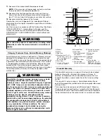
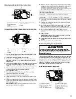
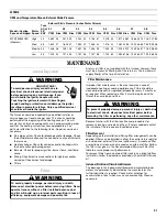
Gas Supply Pressure Measurement
Models Using Single-Stage Gas Control Valves
The line pressure supplied to the gas control valve must be within
the range specified in the Inlet Gas Supply Pressure chart. The
supply pressure can be measured at the gas control valve inlet
pressure tap or at a hose fitting installed in the gas piping drip
leg. The supply pressure must be measured with the unit set to
OFF. To measure inlet pressure, use the following procedure.
100 (30.5)
11
26
55
90
138
255
78
162
307
630
976
125 (38.1)
10
24
48
81
122
224
69
146
275
567
866
150 (45.7)
9
21
43
72
109
202
63
132
252
511
787
200 (61)
8
19
39
66
100
187
54
112
209
439
665
250 (76.2)
8
17
36
60
93
172
48
100
185
390
590
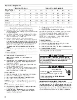
Propane Gas Piping Chart II
Pipe or Tubing
Length—ft (m)
Tubing Size, O.D. Type L
Nominal Pipe Size Schedule 40
³⁄₈
¹⁄₂
⁵⁄₈
³⁄₄
⁷⁄₈
1
¹⁄₈
¹⁄₂
³⁄₄
1 1
¹⁄₄
1
¹⁄₂
Goodman 61
To prevent unreliable operation or equipment damage,
the inlet gas supply pressure must be as specified on the
unit rating plate with all other household gas-fired
appliances operating.
CAUTION
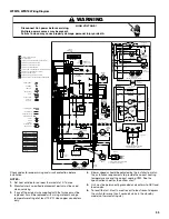
HIGH VOLTAGE!
WARNING
Disconnect ALL power before servicing.
Multiple power sources may be present.
Failure to do so may cause property damage,
personal injury or death.


