


24
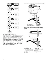
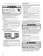
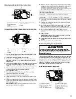
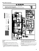
White-Rodgers 36G54 Valve Connected to Manometer
Honeywell VR9205 2-Stage Valve
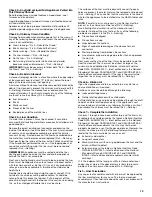
Honeywell VR9205 Valve Connected to Manometer
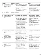
1. Turn off the gas to the furnace at the manual gas shutoff valve
external to the furnace.
2. Connect a calibrated water manometer (or appropriate gas
pressure gauge) at either the gas control valve inlet pressure
boss or the gas piping drip leg. See preceding illustrations for
the location of the inlet pressure boss.
NOTE: If measuring gas pressure at the drip leg on the
Honeywell VR9205 gas control valve, a field-supplied hose
barb fitting must be installed prior to making the hose
connection. If using the inlet pressure boss on the White-
Rodgers 36G54 gas control valve, then use the 36G Valve
Pressure Check Kit.
3. Turn on the gas supply at the manual gas shutoff valve
external to the furnace.
4. Operate the furnace and all other gas-consuming appliances
on the same gas supply line.
5. Measure furnace gas supply pressure with burners firing.
Supply pressure must be within the range specified in the
Inlet Gas Supply Pressure chart.
6. If the supply pressure differs from the chart, make the
necessary adjustments to the pressure regulator, gas piping
size, etc., and/or consult with the local gas utility.
7. Turn off the gas supply to the furnace at the manual shutoff
valve.
8. Disconnect the manometer.
9. Reinstall the plug before turning on the gas supply to the
furnace.
10. Turn off any unnecessary gas appliances stated in Step 4.
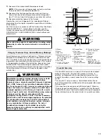
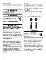
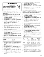
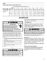
Measuring Inlet Gas Pressure Alternate Method
Gas Manifold Pressure Measurement and Adjustment
A. Open to atmosphere
B. Manometer hose
C. Outlet pressure boss
D. High-fire regulator adjust
E. Regulator vent
F. Low-fire regulator adjust
G. Coaxial coil terminal (M)
H. Common terminal (C)
I. High-fire coil terminal (HI)
J. ON/OFF switch
K. Inlet pressure boss
L. Manometer
A. Regulator vent
B. High-fire regulator adjust tower
C. Low-fire regulator adjust tower
D. ON/OFF switch
A. Open to atmosphere
B. Manometer hose
C. Common terminal (C)
D. High-fire coil terminal (HI)
E. Low-fire coil terminal (LO)
F. Outlet pressure tap
¹⁄₈
" NPT
G. Inlet pressure tap
¹⁄₈
" NPT
H. Manometer
C
D
E
F
G
H
I
J
K
A
L
B
A
B
C
D
i
C
D
E
B
A
H
F
G
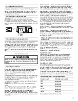
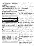
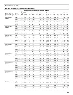
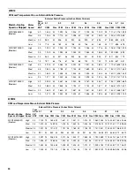
Inlet Gas Supply Pressure
Natural gas
5.0" W.C. minimum; 10.0" W.C. maximum
Propane gas
11.0" W.C. minimum; 13.0" W.C. maximum
A. Gas supply line
B. Gas shutoff valve
C. Gas supply line to furnace
D. Open to atmosphere
E. Manometer
F. Manometer hose
G. Dripleg cap with fitting
A
G
F
E
D
C
B
Goodman 65
To prevent unreliable operation or equipment damage,
the gas manifold pressure must be as specified on the
unit rating plate. Only minor adjustments should be made
by adjusting the gas control valve pressure regulator.
CAUTION


