


34
NOTES:
■
To clear all alarm codes, depress the pushbutton for
6 seconds.
■
LED flash code will cease if power to the control module is
interrupted through the disconnect or door switch.
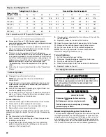
Resetting from Lockout
Furnace lockout results when a furnace is unable to achieve
ignition after 3 attempts. It is characterized by a nonfunctioning
furnace and a 1-flash diagnostic LED code. If the furnace is in
“lockout,” it will (or can be) reset in any of the following ways.
1. Automatic reset. The integrated control module will
automatically reset itself and attempt to resume normal
operations following a 1 hour lockout period.
2. Manual power interruption. Interrupt 115-volt power to the
furnace for 1 to 20 seconds.
3. Manual thermostat cycle. Lower the thermostat so that there
is no longer a call for heat then reset to previous setting.
Interrupt thermostat signal to the furnace for 1 to 20 seconds.
NOTE: If the condition which originally caused the lockout still
exists, the control will return to lockout. See the chart in
“Troubleshooting.”
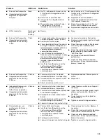
■
Induced draft blower and
circulator blower runs
continuously. No furnace
operation.
■
Integrated control module
diagnostic LED is flashing
5 flashes.
5 flashes
■
Flame sensed with no call for heat.
■
Short to ground in flame sense circuit.
■
Correct short at flame sensor or in flame
sensor wiring.
■
No furnace operation.
■
Integrated control module
diagnostic LED is flashing
6 flashes.
6 flashes
■
Rollout limit switch open.
■
Integrated control module fuse is
blown.
■
Flame rollout.
■
Misaligned burners, blocked flue and/
or air inlet pipe or failed induced draft
blower.
■
Loose or improperly connected wiring.
■
Short in 24-volt AC control circuits or
safety circuits.
■
Faulty rollout limit switch.
■
Check burners for proper alignment.
■
Check flue and air inlet piping for
blockage, proper length, elbows and
termination. Correct as necessary.
■
Check rollout limit switch. Replace, if
necessary.
■
Check induced draft blower for proper
performance. Replace, if necessary.
■
Tighten or correct wiring connection.
■
Repair short in 24-volt AC control and
safety circuit(s).
■
Replace integrated control module fuse
(3A).
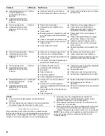
■
Normal furnace operation.
■
Integrated control module
diagnostic LED is flashing
7 flashes.
7 flashes
■
Flame sense microamp signal is low.
■
Flame sensor is coated/oxidized.
■
Flame sensor incorrectly positioned in
burner flame.
■
Lazy burner flame due to improper gas
pressure or combustion air.
■
Sand flame sensor with emery cloth.
■
Inspect for proper sensor alignment.
■
Compare current gas pressure to rating
plate information. Adjust as needed.
■
No furnace operation.
■
Integrated control module
diagnostic LED is flashing
8 flashes.
8 flashes
■
Problem with igniter circuit.
■
Improperly connected igniter.
■
Bad igniter.
■
Poor unit ground.
■
Poor burner ground.
■
Faulty integrated control module.
■
Check and correct wiring from integrated
control module to igniter
■
Replace bad igniter.
■
Check and correct unit ground wiring.
■
Replace bad integrated control module.
■
Induced draft blower runs
continuously. Furnace
fails to operate.
■
Integrated control module
diagnostic LED is flashing
continuously.
Continuous
flashes
■
Polarity of 115- or 24-volt power is
reversed.
■
Polarity of 115-volt AC power to
furnace or integrated control module is
reversed.
■
Red and blue wires to transformer are
reversed.
■
Poor unit ground.
■
Review wiring diagram to correct polarity.
■
Verify proper ground. Correct, if
necessary.
■
Reverse red and blue wires connected to
transformer.
Problem
LED Code
Fault/Cause
Solution


