


8
Plan Vent System
The high efficiency of this furnace is accomplished by the
removal of both sensible and latent heat from the flue gases. The
removal of latent heat results in the condensation of moisture in
the flue gases. This condensation occurs in the secondary heat
exchanger and in the vent system. Therefore, this furnace
requires special venting considerations, and the instructions
must be followed to ensure proper operation. All venting must be
in accordance with the codes having jurisdiction in the area and
these instructions.
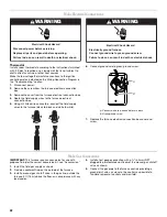
IMPORTANT:
■
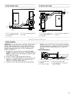
The venting system must be supported with mounting straps
to keep any weight load from being applied to the vent
blower. Horizontal vent pipe must be supported every 5 ft
(1.5 m) and vertical pipe should be supported every 10 ft
(3 m) to avoid sagging and provide rigid support.
■
This furnace must not be connected to any Type B, BW, or
L vent or vent connector and must not be connected to any
portion of a factory-built or masonry chimney.
■
This furnace is not to be common vented with any other
appliance. The vent pipe must not be connected to a
chimney flue serving a separate appliance designed to burn
solid fuel.
Materials
■
All pipe, fittings, primer, and solvent cement must conform
with American National Standard Institute and the American
Society for Testing and Materials (ANSI/ASTM) standards.
The solvent shall be free flowing and contain no lumps,
undissolved particles, or any foreign matter that adversely
affects the joint strength or chemical resistance of the
cement. The cement shall show no gelatinization,
stratification, or separation that cannot be removed by
stirring. See “Piping and Fitting Specifications” for approved
piping and fitting materials.
Piping and Fitting Specifications
■
The primers and solvents used must also meet ASTM
specifications. PVC primer is specified in ASTM F656. Use
PVC solvent as specified in ASTM D2564 and ABS solvent
cement as specified ASTM D2235. Low temperature solvent
cement is recommended. Metal or plastic strapping may be
used for vent pipe hangers.
■
When making ABS joints, pieces can be prepared with a
cleaner. When joining ABS to PVC materials, use PVC solvent
cement as specified in ASTM D3138.
■
Preferred fittings are DWV style or long sweep. Seal all joints
gas tight with appropriate cement. In areas where vent and air
intake pipes are exposed to abnormal stress or are subject to
damage, schedule 80 pipe should be used.
■
Use high temperature RTV silicone sealant to attach the air
intake pipe into the connector on the burner box so the air
intake pipe can be removed if service is required.
NOTE: Do not use cement.
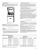
Vent Pipe Size and Length
The vent pipe and air intake pipe (in direct vent installations) should be sized in accordance with the information found in the Vent Table
charts. One 90° elbow is equivalent to 5 ft (1.5 m) of pipe. Two 45° elbows are equivalent to one 90° elbow. The minimum length
certified for use with this furnace is 5 ft (1.5 m) and one elbow, not including the vent and air intake terminals.
Piping and Fitting Material
ASTM Specification
Schedule 40 PVC (Pipe)
D1785
Schedule 40 PVC (Cellular Core Pipe)
F891
Schedule 40 PVC (Fittings)
D2466
SDR-26 (Pipe)
D2241
Schedule 40 ABS (Pipe)
D1527
Schedule 40 ABS (Fittings)
D2468
Schedule 40 & 80 CPVC (Pipe)
F441
ABS-DWV Drain Waste & Vent
(Pipe & Fittings)
D2661
PVC-DWV Drain Waste & Vent
(Pipe & Fittings)
D2665
Vent Table—40,000 to 80,000 Btu/h Models
Vent Pipe Length—ft (m) Minimum Pipe Diameter—in. (cm)
5 (1.5)
1
¹⁄₂
(3.8)
1
¹⁄₂
(3.8)
2 (5.1)
2 (5.1)
2 (5.1)
2 (5.1)
2 (5.1)
2 (5.1)
2 (5.1)
2 (5.1)
10 (3)
1
¹⁄₂
(3.8)
2 (5.1)
2 (5.1)
2 (5.1)
2 (5.1)
2 (5.1)
2 (5.1)
2 (5.1)
2 (5.1)
2 (5.1)
20 (6.1)
2 (5.1)
2 (5.1)
2 (5.1)
2 (5.1)
2 (5.1)
2 (5.1)
2 (5.1)
2 (5.1)
2 (5.1)
2
¹⁄₂
(6.4)
30 (9.1)
2 (5.1)
2 (5.1)
2 (5.1)
2 (5.1)
2 (5.1)
2 (5.1)
2 (5.1)
2
¹⁄₂
(6.4) 2
¹⁄₂
(6.4) 2
¹⁄₂
(6.4)
40 (12.2)
2 (5.1)
2 (5.1)
2 (5.1)
2 (5.1)
2 (5.1)
2
¹⁄₂
(6.4)
2
¹⁄₂
(6.4) 2
¹⁄₂
(6.4) 2
¹⁄₂
(6.4) 2
¹⁄₂
(6.4)
50 (15.2)
2 (5.1)
2 (5.1)
2
¹⁄₂
(6.4)
2
¹⁄₂
(6.4)
2
¹⁄₂
(6.4)
2
¹⁄₂
(6.4)
2
¹⁄₂
(6.4) 2
¹⁄₂
(6.4) 2
¹⁄₂
(6.4) 3 (7.6)
60 (18.3)
2 (5.1)
2
¹⁄₂
(6.4)
2
¹⁄₂
(6.4)
2
¹⁄₂
(6.4)
2
¹⁄₂
(6.4)
2
¹⁄₂
(6.4)
2
¹⁄₂
(6.4) 3 (7.6)
3 (7.6)
3 (7.6)
70 (21.3)
2
¹⁄₂
(6.4)
2
¹⁄₂
(6.4)
2
¹⁄₂
(6.4)
2
¹⁄₂
(6.4)
2
¹⁄₂
(6.4)
3 (7.6)
3 (7.6)
3 (7.6)
3 (7.6)
NR
80 (24.4)
2
¹⁄₂
(6.4)
2
¹⁄₂
(6.4)
2
¹⁄₂
(6.4)
3 (7.6)
3 (7.6)
3 (7.6)
3 (7.6)
3 (7.6)
NR
NR
90 (27.4)
2
¹⁄₂
(6.4)
2
¹⁄₂
(6.4)
3 (7.6)
3 (7.6)
3 (7.6)
3 (7.6)
3 (7.6)
NR
NR
NR
Number of 90º Elbows
0
1
2
3
4
5
6
7
8
9
NR = Not Recommended
Summary of Contents for WFCT
Page 31: ...31 Notes ...