Whirlpool WFCT Installation Instructions Manual Download Page 6

6

Existing Venting Systems

When an existing furnace is removed or replaced, the original 
venting system may no longer be sized to properly vent the 
attached appliances. An improperly sized venting system can 
result in spillage of flue products into the living space, the 
formation of condensate, leakage, etc. See the “Carbon 
Monoxide Poisoning Hazard” for proper test procedure.

 Venting Options

The furnace can be installed as either direct vent or nondirect 
vent furnaces.

For either type of installation, special venting considerations 
must be followed. See “Determine Vent Pipe Direction” section 
for the type of furnace and venting being installed. 

Direct Vent

A direct vent (two pipe) installation requires that all the air 
necessary for combustion be supplied from outside the dwelling 
through an air intake pipe.

All vents passing through floors, ceilings, and walls must be 
installed in accordance with National Fuel Gas Code, ANSI 
Z223.1/NFPA 54 (latest edition). In all applications where the 
flue pipe is run through an unconditioned space, 

¹⁄₂

" (1.3 cm) 

insulation must be used over the pipe. In extremely cold 
climates, 

³⁄₄

" (1.9 cm) insulation is recommended.
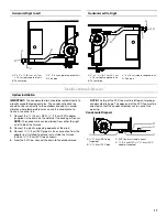
Nondirect Vent 

A nondirect vent (one pipe) installation uses air from inside the 
dwelling for combustion.

The furnace is shipped with the air inlet pipe terminated to the 
top panel for either inside or outside combustion air. An inlet 
air restrictor plate is supplied with this furnace and can be 
found in the plastic bag containing these Installation 
Instructions and the User’s Information Manual.
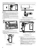
For installations using inside air for combustion (nondirect 
vent), attach a 90° elbow (not supplied) to the inlet coupler 
and install the restrictor plate inside the elbow (see 
“Nondirect Vent Installation”).

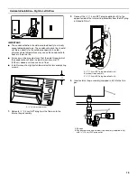
Inlet Air Restrictor Plate

A 2" (5.1 cm) restrictor plate is supplied with the 40, 60, 80 
and 100k Btu/h models. A 3" (7.6 cm) restrictor plate is 
supplied with the 125k Btu/h model.

In horizontal applications, the restrictor plate must be 
secured to the inlet collar by inserting a field supplied piece of 
2" (5.1 cm) or 3" (7.6 cm) PVC pipe into the inlet collar after 
the restrictor plate is installed. Use high temperature RTV 
sealant to attach the PVC to the inlet collar.
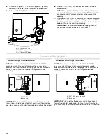
Flue Pipe Screen

A flue pipe screen designed to keep objects out of the flue pipe is 
included in the plastic bag.

In all installations, this screen should be installed at the 
termination of the flue pipe.

Flue Pipe Screen

WARNING:

CARBON MONOXIDE POISONING HAZARD

Failure to follow the steps outlined below for each 
appliance connected to the venting system being 
placed into operation could result in carbon monoxide 
poisoning or death.

The following steps shall be followed for each appliance 
connected to the venting system being placed into operation, 
while all other appliances connected to the venting system are 
not in operation:

1. Seal any unused openings in the venting system.

2. Inspect the venting system for proper size and horizontal 

pitch, as required in the National Fuel Gas Code, 
ANSI Z223.1/NFPA 54 or the CSA B149.1, Natural Gas and 
Propane Installation Codes and these instructions. 
Determine that there is no blockage or restriction, leakage, 
corrosion and other deficiencies which could cause an 
unsafe condition.

3. As far as practical, close all building doors and windows 

and all doors between the space in which the appliance(s) 
connected to the venting system are located and other 
spaces of the building.

4. Close fireplace dampers.

5. Turn on clothes dryers and any appliance not connected to 

the venting system. Turn on any exhaust fans, such as 
range hoods and bathroom exhausts, so they are operating 
at maximum speed. Do not operate a summer exhaust fan.

6. Follow the lighting instructions. Place the appliance being 

inspected into operation. Adjust the thermostat so 
appliance is operating continuously.

7. Test for spillage from draft hood equipped appliances at the 

draft hood relief opening after 5 minutes of main burner 
operation. Use the flame of a match or candle.

8. If improper venting is observed during any of the above 

tests, the venting system must be corrected in accordance 
with the National Fuel Gas Code, ANSI Z223.1/NFPA 54 
and/or CSA B149.1, Natural Gas and Propane Installation 
Codes.

9. After it has been determined that each appliance connected 

to the venting system properly vents when tested as 
outlined above, return doors, windows, exhaust fans, 
fireplace dampers and any other gas-fired burning 
appliances to their previous conditions of use.

Summary of Contents for WFCT

Page 1: ... On 25 Cooling 25 CONTROLS 26 TROUBLESHOOTING 27 ASSISTANCE OR SERVICE 30 Accessories 30 47861B008 Whirlpool Home Cooling and Heating 14610 Breakers Drive Jacksonville FL 32258 Whirlpool and Whirlpool Gold Models WFCT WGFDT You can be killed or seriously injured if you don t immediately You can be killed or seriously injured if you don t follow All safety messages will tell you what the potential ...

Page 2: ...ucts carry air circulated by the furnace to areas outside the space containing the furnace the return air shall also be handled by duct s sealed to the furnace casing and terminating outside the space containing the furnace A gas fired furnace for installation in a residential garage must be installed as specified in the Location Requirements section of these instructions The furnace is not to be ...

Page 3: ...ed here Tools needed Parts needed Check local codes and with gas supplier Check existing gas supply electrical supply and venting and read Ductwork Requirements Electrical Requirements Gas Supply Requirements Venting Requirements and Installation Configurations before purchasing parts Parts supplied Inlet air restrictor plate Flue pipe screen Condensate disposal kit WARNING Gas leaks cannot always...

Page 4: ...not less than 18 45 7 cm above the floor The furnace is to be located or protected to avoid physical damage by vehicles Furnaces may be installed as suspended units in the horizontal position These furnaces are not designed for direct attachment of suspension rods to the furnace casing See installation Configurations If the furnace is to be installed in an attic or other insulated space it must be...

Page 5: ...or in the absence of local codes with the National Electrical Code ANSI NFPA No 70 latest edition In all instances other than wiring for the thermostat the wiring to be done and any replacement of wire shall conform with the temperature limitation for Type T wire 63 F rise The line voltage supply should be routed through a readily accessible disconnect located within sight of the furnace A junctio...

Page 6: ...h temperature RTV sealant to attach the PVC to the inlet collar Flue Pipe Screen A flue pipe screen designed to keep objects out of the flue pipe is included in the plastic bag In all installations this screen should be installed at the termination of the flue pipe Flue Pipe Screen WARNING CARBON MONOXIDE POISONING HAZARD Failure to follow the steps outlined below for each appliance connected to t...

Page 7: ...s are met All provisions for indoor combustion air must meet the requirements for combustion air indicated in the National Fuel Gas Code ANSI Z223 1 NFPA 54 latest edition and or any applicable local codes If indoor combustion air is used the air supply to the furnace should not be exposed to the following substances Permanent wave solutions Chlorinated waxes and cleaners Chlorine based swimming p...

Page 8: ...Metal or plastic strapping may be used for vent pipe hangers When making ABS joints pieces can be prepared with a cleaner When joining ABS to PVC materials use PVC solvent cement as specified in ASTM D3138 Preferred fittings are DWV style or long sweep Seal all joints gas tight with appropriate cement In areas where vent and air intake pipes are exposed to abnormal stress or are subject to damage ...

Page 9: ... terminal location shall comply with the National Fuel Gas Code ANSI Z223 1 or local requirements For informational purposes the side wall terminal vent clearances are shown in the Sidewall Vent Terminal Clearances tables Vent Table 90 000 to 100 000 Btu h Models Vent Pipe Length ft m Minimum Pipe Diameter in cm 5 1 5 NR 2 5 1 2 5 1 2 5 1 2 5 1 2 5 1 2 5 1 2 6 4 2 6 4 2 6 4 10 3 2 5 1 2 5 1 2 5 1 ...

Page 10: ...terminal E Clearance to unventilated soffit F Clearance to outside corner G Clearance to inside corner H Clearance to each side of center line extended above meter regulator assembly I Clearance to service regulator vent outlet J Clearance to nonmechanical air supply inlet to building or the combustion air inlet to any other appliance 6 15 2 cm for appliances less than or equal to 10 000 Btu h 9 2...

Page 11: ...e terminal E Clearance to unventilated soffit F Clearance to outside corner G Clearance to inside corner H Clearance to each side of center line extended above meter regulator assembly I Clearance to service regulator vent outlet J Clearance to nonmechanical air supply inlet to building or the combustion air inlet to any other appliance 48 121 9 cm below or to side of opening 12 30 5 cm above open...

Page 12: ...f the house within the parameters as shown NOTE The 18 45 7 cm dimension shown below is the minimum recommended height for extremely cold areas In these areas moisture in the flue gases may condense and freeze on the air intake if this height is reduced In milder climates this may be reduced to a minimum of 6 15 2 cm Height may be increased as needed provided total length of pipe to furnace is not...

Page 13: ...e flue pipe see Flue Pipe Screen in Venting Requirements should be installed at the termination of the flue pipe Nondirect Vent Upflow Horizontal Venting Nondirect Vent Upflow Vertical Venting A Run pitch 6 4 mm per foot minimum B Flue pipe screen inside flue pipe C 6 15 2 cm D 12 30 5 cm minimum clearance Adjust height to expected snow level based on local conditions E Air intake pipe F Condensat...

Page 14: ...side of the house within the parameters as shown NOTE The 18 45 7 cm dimension shown below is the minimum recommended height for extremely cold areas In these areas moisture in the flue gases may condense and freeze on the air intake if this height is reduced In milder climates this may be reduced to a minimum of 6 15 2 cm Height may be increased as needed provided total length of pipe to furnace ...

Page 15: ...ep objects out of the flue pipe see Flue Pipe Screen in Venting Requirements should be installed at the termination of the flue pipe Nondirect Vent Horizontal Horizontal Venting Horizontal Right to Left Nondirect Vent Horizontal Horizontal Venting Horizontal Left to Right A 6 15 2 cm minimum to roof Adjust height to expected snow level based on local conditions B 6 16 5 cm minimum to 24 61 cm maxi...

Page 16: ...n at the outside end of the flue pipe 7 Make sure all vent connections do not leak 8 Check that the exhaust vent pipe terminates outside the building 9 After the condensate disposal system has been installed prime the trap system by slowly pouring 8 oz 250 mL of water down the vent pipe The vent pipe on horizontal runs must slope upward away from the furnace at a minimum pitch of 6 4 mm per foot o...

Page 17: ...of the drain 3 Connect 1 9 cm PVC pipe make a connection from the adapter just installed to extend just outside the furnace Install a 1 9 cm PVC tee as shown 4 From the PVC tee connect the drain to the disposal area NOTE The top of the PVC tee must be left open for proper condensate drainage The open end of the PVC tee must be oriented so that the condensate does not run out of this opening Conden...

Page 18: ...pplied in kit into flue pan 4 Connect a length of PVC pipe 36 91 4 cm minimum to the external trap assembly supplied in kit 5 Install a 1 9 cm PVC tee as shown 6 From the 1 9 cm PVC tee connect the drain to the disposal area NOTE The top of the PVC tee must be left open for proper condensate drainage The open end of the PVC tee must be oriented so that the condensate does not run out of this openi...

Page 19: ...um of 9 22 9 cm above a surface such as a floor Install furnace at a slight pitch forward with shims or adjusting screws 1 Relocate 1 3 cm NPT plug from the flue pan to the internal trap assembly 2 Connect the 1 3 cm NPT plug supplied in kit to the opposite side of the internal trap assembly from the NPT plug installed in Step 1 3 Insert external trap assembly supplied in kit into the flue pan A 6...

Page 20: ...o the 0 10 W C pressure switch Other end of hose must be connected to external drain trap Route hose through gas line access hole in cabinet Then connect to barbed fitting on drain trap assembly IMPORTANT Be sure that the pressure switch hoses do not form a trap to hold condensation that could result from the flue gas Hose may be cut shorter to avoid forming a trap if required Horizontal Left to R...

Page 21: ...ewed for possible openings using light assistance or so that a probe can be inserted for sampling the airstream The cover for the opening must be leakproof FilterSpecifications Upflow Models A filter rack and cleanable 16 x 25 x 40 6 cm x 63 5 cm x 1 3 cm filter are supplied with this furnace Models designed for more than 1 600 CFM 487 7 m3 min nominal air delivery include two of each Some model f...

Page 22: ...RTANT This furnace requires conversion for use with propane To order the correct conversion kit see Accessories 1 Install the field gas supply as shown 2 Provide a sediment trap on the outside of the furnace 3 Install a manual gas shutoff valve in the gas line outside the furnace 5 ft 1 5 m above the floor or in accordance with any local codes 4 Install a test gauge connection with a 3 2 mm NPT pl...

Page 23: ...al gas and 10 25 4 cm W C for propane gas For natural gas check the furnace rate by observing the gas meter making sure all other gas appliances are turned off The test hand on the meter should be timed for at least one revolution At altitudes from 2 000 to 7 500 ft 609 6 m to 2 286 m the furnace input rate must not exceed that on the rating plate NOTE The actual heating value of your gas can be o...

Page 24: ...equired For the correct orifice size see Table F 4 in Appendix F of the National Fuel Gas Code ANSI Z223 1 NFPA 54 latest edition CompleteInstallation IMPORTANT Do not use this furnace if any part has been under water Immediately call a qualified person to inspect the furnace and to replace any part of the control system and gas control which has been under water 1 Be sure you have all of your too...

Page 25: ...energizes the main valve causing the burners to shut off The induced draft blower shuts off after a 15 second post purge delay The circulating air blower will continue to operate until the user selectable heat blower off delay expires The control returns to standby mode once the heat blower off delay expires FanOn During a fan on call the thermostat energizes the R G circuit of the control board i...

Page 26: ...ns under abnormal reverse airflow conditions that could occur in a counterflow or horizontal installation if the circulating air blower fails It is an automatic reset control Safety Interlock Switch When the blower door is removed the safety interlock switch breaks the power supply to the burner controls and blower motor Ignition Control Board The ignition control board operates the gas valve circ...

Page 27: ...blem occurs a failure code is indicated by the LED on the ignition control board The control continuously monitors its own operation and the operation of the system If a failure occurs the LED will indicate the failure code IMPORTANT Do not remove the blower compartment door or turn off the power to the furnace since either action will clear the control s memory of the fault 1 Start the system by ...

Page 28: ...UM L1 XFMR CONT EAC COOL HEAT Hot Surface Igniter Interlock Switch Line Voltage Factory Line Voltage Field Low Voltage Factory Low Voltage Field Circulation Blower Not on all models Induced Draft Blower Pressure Switch Aux Limit Switch Check codes for proper wiring and circuit protection before installation NOTES 1 Press and release fault code history button to display fault codes To erase codes p...

Page 29: ... Gas Control Valve Flame Sensor Pin 3 Pin 2 Pin 6 Pin 5 Pin 11 Pin 1 Pin 7 Pin 10 Pin 4 Pin 8 Pin 9 Pin 12 If Used Rollout Switch Rollout Switch Hot Surface Igniter Neutrals Humidifier Induced Draft Blower Air Cleaner Heat Cool Blower Motor Transformer 24 VAC 120 VAC Interlock Switch Neutrals Neutrals Neutrals Neutrals Neutrals 120 1 60 ...

Page 30: ...610 Breakers Drive Jacksonville FL 32258 Please include a daytime phone number in your correspondence Accessories To order accessories ask for the appropriate part number listed below or contact your Whirlpool Home Cooling and Heating dealer ALPKT572 3 Natural Gas to Propane Conversion Kit AFILT524 1 Side Return Filter Kit AFILT529 1 Bottom Return Filter Kit ...

Page 31: ...31 Notes ...

Page 32: ...reserved Honeywell is a trademark of Honeywell International Inc Registered Trademark TM Trademark of Whirlpool U S A Manufactured under license by Tradewinds Distributing Company LLC Coconut Grove Florida 3 08 Printed in U S A ...

Reviews: