29
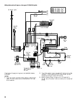
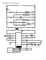
Wiring Schematic—Honeywell
®
VR 8205 System
Pressure Switch
Aux Limit Switch
Condenser
Aux Limit Switch
Limit Switch
If Used
Thermostat
Gas Control Valve
Flame Sensor
Pin 3
Pin 2
Pin 6
Pin 5
Pin 11
Pin 1
Pin 7
Pin 10
Pin 4
Pin 8
Pin 9
Pin 12
If Used
Rollout Switch
Rollout Switch
Hot Surface Igniter
Neutrals
Humidifier
Induced Draft Blower
Air Cleaner
Heat
Cool
Blower Motor
Transformer
24 VAC
120 VAC
Interlock
Switch
Neutrals
Neutrals
Neutrals
Neutrals
Neutrals
120 / 1 / 60
Summary of Contents for WFCT
Page 31: ...31 Notes ...


