


15
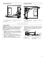
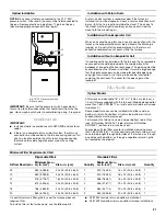
Direct Vent—Horizontal (Vertical Venting—Horizontal Right
to Left)
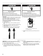
Direct Vent—Horizontal (Vertical Venting—Horizontal Left
to Right)
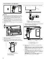
Nondirect Vent Installation—Horizontal Installations
■
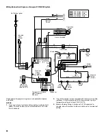
Refer to appropriate tables for proper pipe size, vent length
and the number of elbows allowed.
■
Refer to “Materials” in “Plan Vent System” for the proper
venting material.
■
An inlet air restrictor plate found in the plastic bag containing
these Installation Instructions and the User’s Information
Manual must be installed in all nondirect vent installations.
See “Inlet Air Restrictor Plate” in “Venting Requirements”.
Install the inlet air restrictor plate inside the inlet coupler.
Attach a 90° elbow (not supplied) to the inlet coupler.
■
The flue pipe screen, designed to keep objects out of the flue
pipe (see “Flue Pipe Screen” in “Venting Requirements”),
should be installed at the termination of the flue pipe.
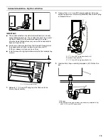
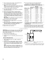
Nondirect Vent—Horizontal (Horizontal Venting—
Horizontal Right to Left)
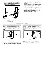
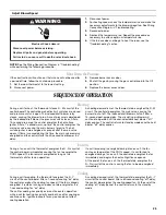
Nondirect Vent—Horizontal (Horizontal Venting—
Horizontal Left to Right)
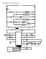
A. 6" (15.2 cm) minimum
to roof. Adjust height
to expected snow level
based on local
conditions.
B. 6
¹⁄₂
" (16.5 cm) minimum to 24" (61 cm)
maximum
C. Drain tee (in kit)
D. 3" (7.6 cm) long piece of 2" (5.1 cm)
diameter pipe
C
D
B
A
A. 6" (15.2 cm) minimum to roof. Adjust
height to expected snow level based on
local conditions.
B. 6
¹⁄₂
" (16.5 cm) minimum to 24" (61 cm)
maximum
C. Drain tee (in kit)
D. 3" (7.6 cm) long piece of
2" (5.1 cm) diameter pipe
C
D
B
A
A. Inlet air restrictor plate
(inside inlet coupler)
B. 3" (7.6 cm) long piece of 2" (5.1 cm)
diameter pipe
C. Drain tee (in kit)
C
B
A
A. 3" (7.6 cm) long piece of 2" (5.1 cm)
diameter pipe
B. Drain tee (in kit)
C. Inlet air restrictor plate
(inside inlet coupler)
D. 6" (15.2 cm)
A
B
D
C
Summary of Contents for WFCT
Page 31: ...31 Notes ...