


20
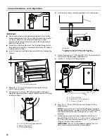
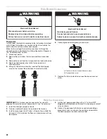
4. Connect a length of
³⁄₄
" (1.9 cm) PVC pipe (36" [91.4 cm]
minimum) to the external trap assembly (supplied in kit).
5. Install a
³⁄₄
" (1.9 cm) PVC tee as shown.
6. From the
³⁄₄
" (1.9 cm) PVC tee, connect the drain to the
disposal area.
NOTE: The top of the PVC tee must be left open for proper
condensate drainage. The open end of the PVC tee must be
oriented so that the condensate does not run out of this
opening.
7. Remove vinyl hose from kit and cut in half. Connect one end
of the hose to the
³⁄₈
" (1 cm) barbed fitting on the vent PVC
tee. Connect the other end of the vinyl hose to the
³⁄₈
" (1 cm)
barbed fitting on the drain trap assembly.
IMPORTANT: Be sure to avoid double-trapping the vinyl
hose. Hose must be installed as shown above.
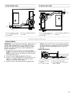
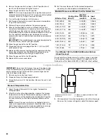
Connection to Pressure Switch
Horizontal Right to Left Installation
NOTE: Black hose is factory-connected to the 0.10" W.C.
pressure switch. Other end of hose must be connected to
external drain trap. Route hose through gas line access hole in
cabinet. Then connect to
¹⁄₄
" barbed fitting on drain trap
assembly.
IMPORTANT: Be sure that the pressure switch hoses do not
form a trap to hold condensation that could result from the flue
gas. Hose may be cut shorter to avoid forming a trap, if required.
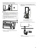
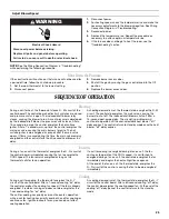
Horizontal Left to Right Installation
NOTE: Black hose is factory-connected to the 0.10" W.C.
pressure switch. Other end of hose must be connected to
external drain trap. Route hose through gas line access hole in
cabinet. Then connect to
¹⁄₄
" barbed fitting on drain trap
assembly.
IMPORTANT: Be sure that the pressure switch hoses do not
form a trap to hold condensation that could result from the flue
gas. Hose may be cut shorter to avoid forming a trap, if required.
A.
³⁄₄
" (1.9 cm) PVC tee
B. 36" (91.4 cm) piece of
³⁄₈
" vinyl tubing
C.
³⁄₄
" (1.9 cm) PVC pipe
A
B
C
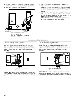
A. 0.10" W.C. pressure switch
B. Black hose
A
B
A. 0.10" W.C. pressure switch
B. Black hose
A
B
Summary of Contents for WFCT
Page 31: ...31 Notes ...