background image

15

Fiber Optic Cable Sensor

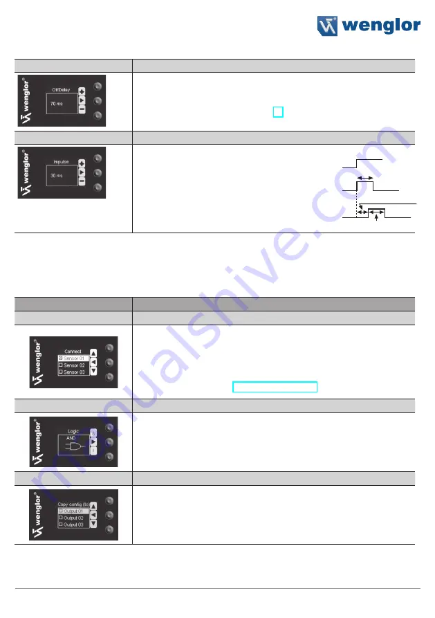
Off-Delay

Adjusting Off-Delay

Off-delay can be adjusted within a range of 0 to 10000 ms by pressing  
the + or – key.* Off-delay is disabled if a impulse duration has already 
been selected. See figure 4 on page 16.

Impulse

Adjusting Impulse Duration
Pulse duration defines how long the output  
signal remains in the activated state. A impulse  
length can be selected within a range  
of 0 to 10000 ms by pressing the + or – key.*  
After the selected pulse duration has elapsed,  
the output signal is returned  
to the deactivated state.

(Description applies to NO contacts in scanning  
mode or NC contacts in barrier mode.)

* Press and hold the + or – key in order to scroll quickly through the numbers.

6.3.2 Link the outputs
The outputs can be linked to one or more Sensors, or to the speed measurement function.

Function

Description

Sensors

Select the Sensors to be linked

The Sensors to be linked are selected in the  select list den with the  
navigation keys and the enter key. One or maximal all connected Sensors 
can be selected. 

Also “Measure” can be selected to link the speed measurement function 
to an output. See section “Measure” on page 16.

Logic

Selecting the Linkage Logic

By pressing the & key and the I key the logic by which the selected 
Sensors are linked is selected. The respective symbol is displayed.

Copy Configurations

Copy Configurations to other Outputs

The configurations of one output are copied to one or several other out-
puts. Therefor the output/s where the configuration should be copied are 
selected with the keys 

5

 and 

6

 and the enter key. Select <Copy with 

key 

5

 and 

6

 and confirm by pressing the enter key.

Function can be  
combined with  
ON-Delay

Summary of Contents for ODX402P0088

Page 1: ...ODX402P0099 Fiber Optic Cable Sensor Operating Instructions EN Translation of the Original Operating Instruction Subject to change without notice Available as PDF version only Status 07 11 2017 www w...

Page 2: ...e mounting 8 4 8 3 Connecting the plastic fibre optic cable 8 5 Initial Start Up 9 5 1 Overview of functions 9 5 2 Menu Structure 10 6 Settings 11 6 1 Run 11 6 2 Sensors 11 6 2 1 Teach In 11 6 2 2 Con...

Page 3: ...perating instruction is part of the product and must be kept during its entire service life Read this operating instruction carefully before using the product Installation start up and maintenance of...

Page 4: ...s Plug number 1 Plug number 2 Plug number 3 775 Supply Voltage A Switching Output 1 2 3 IO Link A Switching Output 1 2 3 Contamination Output Error Output NC Supply Voltage 0 V 4 2 Housing Dimensions...

Page 5: ...0 V Current Consumption Ub 24 V 70 mA 10 mA per ODX402P0099 Switching Frequency 2 kHz Response Time 250 s 70 s per ODX402P0099 ON OFF Delay 0 10000 ms Temperature Drift 10 Temperature Range 25 60 C Sw...

Page 6: ...erated within the unreliable range Unreliable range contamination misalignment 4 6 Complementary Products see catalog wenglor offers Connection Technology for field wiring Suiting Connection Technolog...

Page 7: ...standards and safety precautions must be adhered to when installing and operating the Sensor The Sensor must be protected against mechanical influences Install the device such that its installation po...

Page 8: ...sor 4 8 3 Connecting the plastic fibre optic cable Please cut the plastic fibre optic cable once before using with the Z0015 cutting tool Open the mounting slide with a screwdriver see fig 3 1 Insert...

Page 9: ...uration menu is exited The keys are used for navigation and for configuring settings The functions of the navigation keys vary from menu to menu The functions of the keys appear in the display as foll...

Page 10: ...10 Initial Start Up 5 2 Menu Structure normal Signal Strength Switching Status Indicator Connect only after Window Teach...

Page 11: ...Description T Normal Normal Teach In The object is taught in by pressing the T key Align the spot to the object Briefly press the T key The switching distance to the object is set If necessary readju...

Page 12: ...T Background Background Teach In The background is taught in by pressing the T key like this a quasi background suppression is possible Align the spot to the background e g conveyor belt Briefly press...

Page 13: ...y By pressing the key 5 and 6 the desired operating mode is selected and confirmed by pressing the Enter key High Sensitivity Highest sensitivity for large ranges Normal Sensitivity Normal sensitivity...

Page 14: ...he Output Function Description PNP NPN Selecting the Output Type The output is preset to PNP Pressing the key sets the output to push pull Pressing the key again sets the output to NPN The respective...

Page 15: ...s can be linked to one or more Sensors or to the speed measurement function Function Description Sensors Select the Sensors to be linked The Sensors to be linked are selected in the select list den wi...

Page 16: ...4 Measure Distance Measuring point 1 Measuring point 2 In the menu Measure the speed measurement function is set This function measures the time between the interruption of measurement point one and m...

Page 17: ...under the connected Sensors Edge Set Edge For the determination of the speed the rising positive or the falling negative edge of des switching signal can be used By pressing the key and the rising or...

Page 18: ...ey Mode Select the Display Mode By pressing the key 5 and 6 the display mode is selected and confirmed by pressing the enter key The selectable modes are Sensors Status of the Sensors view elements is...

Page 19: ...as soon as it has been selected Selectable languages German English French Spanish The display language must be selected after initial start up and after each reset 6 7 Information The following info...

Page 20: ...bling the Sensor The Sensor is disabled without interrupting supply power The Sensor is disabled by pressing the enter key and the password entry window is displayed immediately The Sensor is switched...

Page 21: ...generally attributed to the closest output that is still free In the menu Outputs this attribution can be changed In the menu Sensors the Add on Module can be configured Therefor the Sensor has to be...

Page 22: ...and the display and to check the plug connections at regular intervals Do not clean with solvents or cleansers which could damage the product 10 Proper Disposal wenglor sensoric gmbh does not accept...

Page 23: ...23 Fiber Optic Cable Sensor...

Reviews: