CELL CLEANING
Phosphoric acid
or muriatic acid
In.clear includes a self-cleaning feature to prevent scale
deposits on the graphite electrodes of the in.clear system.
However, deposits may still form due to hard water. If that
happens the cell should be cleaned in an acidic solution.
All power must be disconnected before any service proce-
dure is performed.
Disconnect the communication cable and power cable of the
in.clear unit.
TO CLEAN THE IN.CLEAR CELL, FOLLOW THESE
STEPS:
• To remove scales from the cell, we recommend using
phosphoric acid (non-diluted) as the preferred cleaning
product.
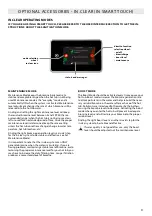
• Close the hot tub flow shut off valves. Unscrew both unions
from the unit and remove the cell from the hot tub equip-
ment compartment.
• Install the rubber washer and the plastic nut on the thread-
ed end of the cell. Tighten plastic nut firmly.
• Place the cell vertically with the cap end down into a plastic
19 L (5 U.S. gallon) bucket and carefully pour the acid
solution into the cell until the 4 plates are covered (careful
not to overflow). The acid solution will begin to produce
bubbles to clean the electrodes.
A foaming action will follow, which is caused by the scale
deposits being dissolved from the plates. If rigorous
foaming action does not begin, the cell does not need to be
cleaned. Rinse and reinstall the cell.
• Allow the electrodes to remain in the solution until the
foaming has stopped. However, DO NOT leave in acid for
more than fifteen minutes. Excessive acid cleaning will
damage the electrolytic cell.
• Pour the acid solution back into the bucket and rinse the
cell thoroughly with clean tap water. If deposits are still vis-
ible, repeat operation for fifteen minutes maximum (some
acid may need to be added to the solution).
• Remove the plastic nut and washer from the cell and keep
them for future cell cleaning.
• Rinse the in.clear with fresh water.
• Re-install the in.clear unit into hot tub system plumbing,
tighten all connections by hand. Open the hot tub flow
shut off valves.
• Reconnect the keypad and power cable.
• Turn power on and start up the pump. Check the keypad
to see that the bromine generation LED is on and resume
normal operation.
OPTIONAL ACCESSORIES - IN.CLEAR
Refer to acid manufacturer's instructions.
Wear eye protection and rubber gloves during these
operations. Splashing or spilling acid can cause severe
personal injuries and/ or property damage.
Always work in a well-ventilated area.
Always add acid to the water; never add water to the
acid.
Do not pour acid outside of the unit where the connec-
tors are located.
Never use acetic acid to clean the cell, as this will cause
permanent damage to cell components and void the
warranty.
96
Summary of Contents for Amazon W-Flow
Page 1: ...USER MANUAL FOR HOT TUB CONTROL SYSTEMS KEYPADS ACCESSORIES ...
Page 19: ...MAJOR COMPONENTS OF THE PRODUCT 19 OLYMPUS ...
Page 20: ...MAJOR COMPONENTS OF THE PRODUCT 20 MONT BLANC ELBRUS 230 ...
Page 21: ...MAJOR COMPONENTS OF THE PRODUCT 21 MONTE BIANCO DISCOVERY ...
Page 22: ...MAJOR COMPONENTS OF THE PRODUCT 22 MONTE ROSA KILIMANJARO ...
Page 23: ...MAJOR COMPONENTS OF THE PRODUCT 23 PARIS ELBRUS 2018 ...
Page 24: ...MAJOR COMPONENTS OF THE PRODUCT 24 LONDON MALAGA 2018 ...
Page 25: ...MAJOR COMPONENTS OF THE PRODUCT 25 MILAN PALERMO 2018 ...
Page 26: ...MAJOR COMPONENTS OF THE PRODUCT 26 BERLIN MARBELLA 2018 ...
Page 27: ...MAJOR COMPONENTS OF THE PRODUCT 27 TAURUS KILIMANJARO ...
Page 28: ...MAJOR COMPONENTS OF THE PRODUCT 28 LIBRA ELBRUS 230 ...
Page 29: ...MAJOR COMPONENTS OF THE PRODUCT 29 HERCULES ...
Page 30: ...MAJOR COMPONENTS OF THE PRODUCT 30 LEO P P ...
Page 31: ...MAJOR COMPONENTS OF THE PRODUCT 31 LEO SCANDI PACK ...
Page 32: ...MAJOR COMPONENTS OF THE PRODUCT 32 ORION P P ...
Page 33: ...MAJOR COMPONENTS OF THE PRODUCT 33 ORION SCANDI PACK ...
Page 34: ...MAJOR COMPONENTS OF THE PRODUCT 34 RIO GRANDE W FLOW ...
Page 35: ...MAJOR COMPONENTS OF THE PRODUCT 35 AMAZON W FLOW ...
Page 36: ...MAJOR COMPONENTS OF THE PRODUCT 36 DANUBE W FLOW ...
Page 133: ...W3000 W5000 WIRING DIAGRAM W3000 W5000 133 ...
Page 136: ...WIRING DIAGRAM W8000 136 ...
Page 143: ......

