54
TROUBLESHOOTING GUIDE, CONT’D.
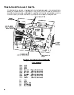
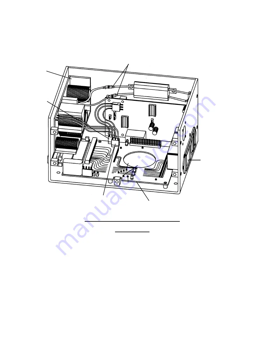
The Modular Drive System is equipped with internal fault diagnostic LEDs and test Points
10 Speed troubleshooting as shown below. Test point evaluation should be performed by
a qualified technician using a volt meter. If a qualified technician is not available, return the
unit to the factory for repair. Always unplug the power cord before opening the case.
Figure 1. Troubleshooting Test Points
TEST POINTS
TP1 -15V
TP2 GND
TP3 +15V
TP4 Tractor + Speed Command
TP5 Tractor - Speed Command
TP6 Weaver + Speed Command
TP7 Weaver - Speed Command
TP8 Height + Speed Command
TP9 Height - Speed Command
L1 -15v
L2 +15V
L3 Height Off
L4 Weaver Off
L5 Tractor Off
INTERCONNECT
CARD
POWER SUPPLY
OUTPUT CONNECTOR
POWER
ENTRY
MODULE
RFI FILTER OUTPUT
POWER
SUPPLY
SPEED CARD
INPUT POWER
CONNECTOR
TP9
TP4
TP5
L2
L1
TP1
TP6
TP3
TP2
L3
L4
L5
RFI FILTER
SPEED
CARD
TP8

