21
WAS.handling Electro Documentation
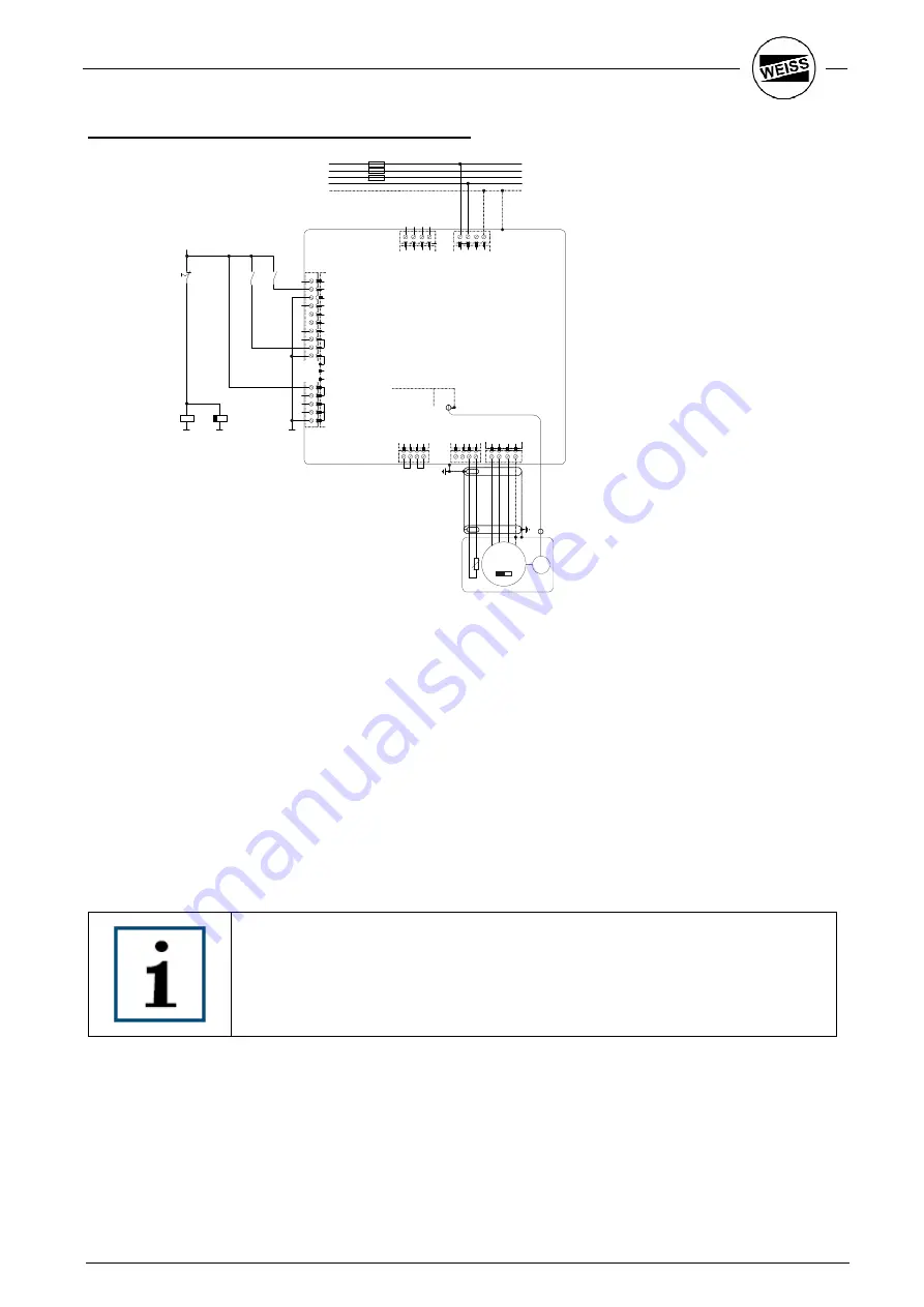
Version 3b: Additional wiring of the Quickstop input
L
3
P
E
L
2
/
N
L
1
+
D
C
2
+
D
C
2
-D
C
1
-D
C
1
X2
X3
ACOPOS
X1
Trigger 1
1
Quickstop
2
COM (1, 2)
3
Shield
4
Endlagensc
5
Endlagenschalter -
6
Referenzschalter
7
Enable
8
Enable
9
COM (8, 9)
10
COM (8, 9)
11
n.c.
12
24V OUT
13
+24V
14
+24V
15
COM (5-7, 13-15)
16
COM (5-7, 13-15)
17
COM (5-7, 13-15)
18
M
3 ~
T
T
V
X5
U
W
P
E
T
-
T
+
B
-
B
+
X4b
X4a
S
3
S
4
S
1
S
2
4
3
2
1
4
3
2
1
4
3
2
1
Slot 1
Slot 2
Slot 3
AC120
Encoder
PLC
AC140
4
3
2
1
4
3
2
1
NOT-AUS
K2
L 1
L 2
L 3
N
PE
K2
K3
1)
24V
K3
GND
1)
The relays K2 / K3 must fulfill the respective safety category..
When the E-Stop switch S1 is pressed, the relay K2 is released. This triggers an active braking via the
ACOPOS input “Quickstop” (clamp X 1/2). If the drive etc. fails, the release-delayed auxiliary relay K3 is
released after a defined time period and causes a shutdown of the energy supply to the motor (clamp X 1/9).
The delay time is set to the calculated time for the stop ramp (max. 0,1s for the horizontal Axes of the HP140).
Thus the shortest possible braking distance is achieved.
Loose of 24V or faults like Overtemperature will cut the Quickstop – ramp.
With use of this wiring, the Axes will not run their blocks. On switching Power of, the vertical axis will be hold or
pushed to the top by a spring (depending on position and load).
At switching on the Axis, their position was lost. It is necessary to do a homing (no referencing).
The “Quickstop” input must be configured by the windows program. => see
Documentation for Windows – Program
Summary of Contents for HP140
Page 1: ...04 2010 ...
Page 15: ...WAS handling Electro Documentation 12 Drilling template Fixing screws M5 ...
Page 17: ...WAS handling Electro Documentation 14 Drilling template Fixing screws M5 ...
Page 20: ...17 WAS handling Electro Documentation ACOPOS 1022 three phase connection 3 x 400V 480V ...
Page 46: ...43 WAS handling Electro Documentation ...
Page 47: ......
Page 48: ......


