- 20 -
8
Interface Description IO-Link
The interface description of the IO-Link interface is defined in the IO-Link Device Description (IODD) file that
belongs to the gripping module. The IODD file that is needed for the configuration of the gripping module
can be found on our website at
https://www.weiss-robotics.com/ieg
under
“
Downloads
”
.
8.1
Cyclic Process Data
Please pay attention to the byte order. According to the IO-Link standard, data is transmitted in big-
endian format.
8.1.1
Output Data (IO-Link Master to Gripping Module)
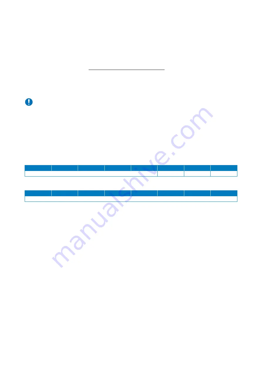
Table 8 describes the cyclic process data (2 byte) that the gripping module expects from the IO-Link master.
BYTE 0
15
14
13
12
11
10
9
8
RES
HOME
EN
CMD
BYTE 1
7
6
5
4
3
2
1
0
INDEX
Table 8: Process data word IO-Link master to gripping module
RES
–
Reserved data bits (bit 15…11)
These data bits are reserved and are currently not evaluated by the gripping module. Their value
should always be set to 0 by the master.
HOME - Reference gripping module (bit 10, BooleanT)
If this bit is set and the gripping module is activated (EN = 1), a reference run is performed. In normal
operation, this bit must be reset to 0. The reference run is described in chapter 9.3.
EN - Activate gripping module (bit 9, BooleanT)
This bit must be set so that movement commands can be executed. If the bit is not set, the drive is de-
activated and the fingers are force-free.
CMD - Gripping command (bit 8, BooleanT)
With this bit, the gripping and releasing of parts is controlled. If the bit is set, the gripping module grips
with the grip that has been selected via INDEX; otherwise the module releases a gripped part.


