Weidmuller Wireless Ethernet Modem & Device Server WI-MOD-E-G/A User Manual
Rev.
2.16
www.weidmuller.com
72
Open configuration webpage with Internet Explorer at address https://192.168.0.1XX/ where XX is the last two digits of the
module’s serial number
When prompted for password, enter default username “user” and password “user”
Click “Network”, and select Operating Mode as Access Point.
Select Device Mode as Bridge.
Change the Gateway IP Address to 192.168.0.1
Change the Ethernet and Wireless IP addresses to 192.168.0.200
Change Ethernet and Wireless Subnet masks to 255.255.255.0
Enter a System Address (ESSID) string
Select the Radio Encryption required.
Set dipswitch to RUN
Save the changes and unit will restart with new settings.
Client 1 Configuration
Perform the same configuration steps as the Access Point configuration with the following differences:
Set the Ethernet and Wireless IP addresses of WI-MOD-E to 192.168.0.201
Set the Operating Mode to Client.
Ensure the ESSID and Radio Encryption method match the Access Point.
If encryption is used, ensure the encryption keys or passphrase match the Access Point.
Client 2 Configuration
As above, however set the Ethernet and Wireless IP addresses as 192.168.0.202
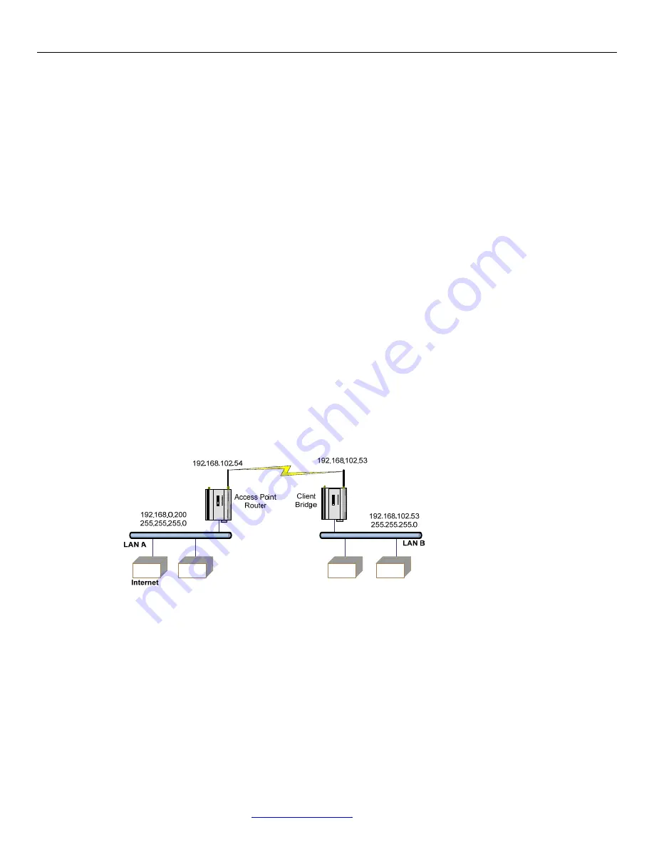
Connecting separate networks
LAN A Configuration
In this example, LAN A is connected to the internet via a router at IP address 192.168.0.1.
Devices on LAN A that only require access to devices on LAN A and B, should have their gateway IP address set to the
WI-MOD-E Access Point as 192.168.0.200.
Devices on LAN A, that must interact with devices on LAN A and B and the internet should set the internet router
192.168.0.1 as their gateway, and must have a routing rule established for devices on LAN B. On PCs, this may be
achieved with the MS-DOS command ROUTE. For this example use: ROUTE ADD 169.254.102.0 MASK 255.255.255.0
192.168.0.200
LAN B Configuration
All devices on LAN B should be configured so their gateway IP address is that of the WI-MOD-E Access Point as
169.254.102.54
Access Point Configuration
Figure 65 - Example Config 2


