


V/f Scalar Control
9-4 | CFW500
9
P0136 – Manual Torque Boost
Adjustable
Range:
0.0 to 30.0 %
Factory
Setting:
According to
inverter model
Properties:
V/f
Access Groups
via HMI:
BASIC, MOTOR
Description:
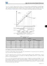
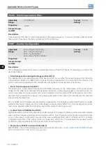
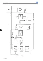
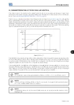
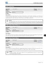
This parameter actuates in low speeds, that is, in the range from 0 Hz to P0147, increasing the inverter output
voltage to compensate the voltage drop in the motor stator resistance so as to keep the torque constant.
The optimum setting is the smallest value of P0136 which allows the motor satisfactory start. A value greater
than necessary will excessively increase the motor current at low speeds, which may lead the inverter to a fault
condition (F0048, F0051 or F0070) or alarm condition (A0046, A0047 or A0050), as well as motor overheating.
shows the region of actuation of the Torque Boost between points P
0
and P
1
.
P0134
P0145
P0146
P0147
P
0
P
1
P
2
P
3
P
4
P0142
P0143
P0144
P0136
Output
frequency (Hz)
Output
voltage (%)
Figure 9.3:
Torque boost region
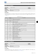
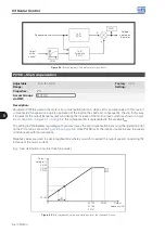
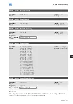
P0142 – Maximum Output Voltage
P0143 – Intermediate Output Voltage
P0144 – Minimum Output Voltage
Adjustable
Range:
0.0 to 100.0 %
Factory
Setting:
P0142 = 100.0 %
P0143 = 66.7 %
P0144 = 33.3 %
Properties:
cfg, V/f
Access Groups
via HMI:
Description:
These parameters allow adjusting the inverter V/f curve together with its orderly pairs P0145, P0146 and P0147.
Summary of Contents for CFW500 V1.8X
Page 2: ......
Page 4: ......
Page 8: ...Contents...
Page 34: ...General Information 2 4 CFW500...
Page 38: ...About the CFW500 3 4 CFW500 3...
Page 42: ...HMI and Basic Programming 4 4 CFW500 4...
Page 52: ...Programming Basic Instructions 5 10 CFW500 5...
Page 56: ...Identification of the Inverter Model and Accessories 6 4 CFW500 6...
Page 76: ...Available Motor Control Types 8 4 CFW500 8...
Page 84: ...V f Scalar Control 9 8 CFW500 9...
Page 170: ...Communication 17 8 CFW500 17...