


Functions Common to All the Control Modes
CFW500 | 11-9
11
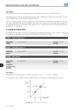
P0320 – Flying Start (FS) / Ride-Through (RT)
Adjustable
Range:
0 = Inactive
1 = Flying Start
2 = Flying Start / Ride-Through
3 = Ride-Through
Factory
Setting:
0
Properties:
cfg
Access Groups
via HMI:
Description:
Parameter P0320 selects the use of the Flying Start and Ride-Through functions. More details in the following
sections.
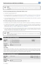
P0331 – Voltage Ramp for FS and RT
Adjustable
Range:
0.2 to 60.0 s
Factory
Setting:
2.0 s
Properties:
Access Groups
via HMI:
Description:
This parameter determines the rising time of the output voltage during the execution of the Flying Start and
Ride-Through functions.
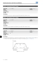
11.4.1 Flying Start Function
In order to activate this function, just program P0320 in 1 or 2; thus the inverter will impose a fixed frequency at
the start, defined by the speed reference, and apply the voltage ramp defined in parameter P0331. In this way,
the start current is reduced. On the other hand, if the motor is at rest, the speed reference and the real speed of
the motor are very different or the direction of rotation is inverted; the result in such cases may be worse than the
conventional start without Flying Start.
The Flying Start function is applied on loads with high inertia or systems that require start with the motor
spinning. Besides, the function may be deactivated dynamically by a digital input P0263 to P0270 programmed
for “24 = Disable Flying Start”. In this way, the user may activate the function in a convenient way according to
the application.
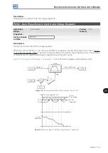
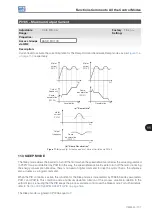
11.4.2 Ride-Through Function
The Ride-Through function will disable the inverter output pulses (IGBT) as soon as the supply voltage reaches a
value below the undervoltage value. A fault due to undervoltage (F0021) does not occur and the DC link voltage will
slowly drop until the supply voltage returns. In case it takes the supply voltage too long to return (over 2 seconds),
the inverter may indicate F0021 (undervoltage on the DC link). If the supply voltage returns before, the inverter will
enable the pulses again, imposing the speed reference instantly (like in the Flying Start function) and making a
voltage ramp with time defined by parameter P0331. Refer to
.
Summary of Contents for CFW500 V1.8X
Page 2: ......
Page 4: ......
Page 8: ...Contents...
Page 34: ...General Information 2 4 CFW500...
Page 38: ...About the CFW500 3 4 CFW500 3...
Page 42: ...HMI and Basic Programming 4 4 CFW500 4...
Page 52: ...Programming Basic Instructions 5 10 CFW500 5...
Page 56: ...Identification of the Inverter Model and Accessories 6 4 CFW500 6...
Page 76: ...Available Motor Control Types 8 4 CFW500 8...
Page 84: ...V f Scalar Control 9 8 CFW500 9...
Page 170: ...Communication 17 8 CFW500 17...