


Digital and Analog Inputs and Outputs
12-22 | CFW500
12
m) NO EXTERNAL FAULT
If DIx is inactive, the inverter will activate the external fault F0091. In this case, the PWM pulses are disabled
immediately.
n) FAULT RESET
Once the inverter is in the fault status and the fault origin condition is no longer active, the fault status will be reset
in the transition of the DIx programmed for this function.
o) USE OF SoftPLC
Only the digital input status DIx in P0012 is used for the SoftPLC functions.
p) MAN/AUTO PID
It allows selecting the inverter speed reference when the PID function is active (P0203 = 1, 2 or 3) between the
reference defined by P0221/P0222 (Manual mode - DIx Inactive) and the reference defined by the PID controller
output (Automatic mode - DIx Active). For further details, refer to
Chapter 13 PID CONTROLLER on page 13-1
.
q) DISABLE FLYING START
It allows the DIx, when active, to disable the action of the Flying Start function preset in parameter P0320 = 1 or 2.
When the DIx is inactive, the Flying Start function operates normally again. Refer to
.
r) LOCK PROG
When the DIx input is active, parameters cannot be changed, no matter the values set in P0000 and P0200.
When the DIx input is Inactive, the modification of parameters will depend on the values set in P0000 and P0200.
s) LOAD Us. 1
This function allows selecting the user 1 memory, process similar to P0204 = 7, with the difference that the user
is loaded from a transition in the DIx programmed for this function.
t) LOAD Us. 2
This function allows selecting the user 2 memory, process similar to P0204 = 8, with the difference that the user
is loaded from a transition in the DIx programmed for this function.
P0204 = 9
P0204 = 10
P0263 to P0270 = 28
P0263 to P0270 = 27
User 1
User 2
Active
Active
Inactive
Inactive
DIx
DIx
Inverter
parameters
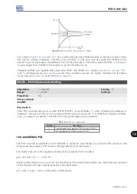
Figure 12.15:
Block diagram of the functions us. 1 and us. 2
u) PTC
The DIx digital inputs can read the resistance of a triple thermistor according to resistance values specified in the
DIN 44081 and 44082 standards, as well as IEC 34-11-2. To do so, just connect the triple thermistor between the
DIx input and the GND (0 V), besides programming the referred DIx for PTC (29).
The PTC thermistor can be used in any DIx, except in the DI2, which has a different input circuit for frequency input.
Therefore, if the DI2 input is programmed for PTC (P0264 = 29), the inverter goes into the config (CONF) status.
Summary of Contents for CFW500 V1.8X
Page 2: ......
Page 4: ......
Page 8: ...Contents...
Page 34: ...General Information 2 4 CFW500...
Page 38: ...About the CFW500 3 4 CFW500 3...
Page 42: ...HMI and Basic Programming 4 4 CFW500 4...
Page 52: ...Programming Basic Instructions 5 10 CFW500 5...
Page 56: ...Identification of the Inverter Model and Accessories 6 4 CFW500 6...
Page 76: ...Available Motor Control Types 8 4 CFW500 8...
Page 84: ...V f Scalar Control 9 8 CFW500 9...
Page 170: ...Communication 17 8 CFW500 17...