


PID Controller
13-2 | CFW500
13
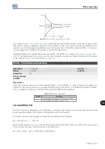
and the ramp input becomes the setpoint directly (bypass operation).
The digital outputs DO1 to DO5 can be set to activate logics of comparison to the process variable (VP), and the
value 22 (=VP>VPx) or 23 (=VP<VPx) must be programmed in one of the respective parameters (P0275 to P0279).
E
na
ble
None
P
ID v
ia A
I1
P
ID v
ia A
I3
P
ID v
ia F
I
S
ele
ct
ion
o
f P
ID
fun
ct
ion
a
nd
fe
edb
ac
k
Se
tpo
in
t d
ef
ini
tio
n
(Pr
oc
es
s v
ar
ia
bl
e re
fe
re
nc
e)
R
ef
er
en
ce (
Lo
ok a
t
)
S
et
po
in
t r
ef
er
en
ce (
Lo
ok a
t
)
Ma
nu
al
(D
Ix
o
pe
n)
A
ut
oma
tic
(DI
x c
lo
se
d)
f*
(L
oo
k a
t
a
nd
)
Fr
equ
enc
y
re
fe
re
nc
e
(spe
ed)
A
ca
de
m
ic
PI
D
A
ca
de
m
ic
PI
D
P
ID
c
on
tr
ol
le
r
act
ion
t
yp
e
0 = D
ire
ct
1 = R
ev
er
se
E
na
ble
P
00
41
P
02
03 = 0
P
02
03 = 1
P
02
03 = 2
P
02
03 = 3
P
02
21 / P
02
22 > 0
P
013
3,
P
013
4
P
02
21 / P
02
22 = 0
P
05
28
P
05
29
P
00
41
–1
P
05
27
P
05
22
P
05
20
P
05
21
P
05
25
P
05
26
D
Ix
Figure 13.1:
Block diagram of the PID controller
Summary of Contents for CFW500 V1.8X
Page 2: ......
Page 4: ......
Page 8: ...Contents...
Page 34: ...General Information 2 4 CFW500...
Page 38: ...About the CFW500 3 4 CFW500 3...
Page 42: ...HMI and Basic Programming 4 4 CFW500 4...
Page 52: ...Programming Basic Instructions 5 10 CFW500 5...
Page 56: ...Identification of the Inverter Model and Accessories 6 4 CFW500 6...
Page 76: ...Available Motor Control Types 8 4 CFW500 8...
Page 84: ...V f Scalar Control 9 8 CFW500 9...
Page 170: ...Communication 17 8 CFW500 17...