V/f Scalar Control
9-2 | CFW500
9
Ou
tp
ut
c
ur
ren
t
lim
ita
tio
n
P
ow
er
s
upp
ly
f*
f
r
f
slip
m
lxR
f
o
P
000
2
m
P
000
7
f
Ud
f
Ud
U
d
U
d
U
d
U
d
f
V
V/
f c
ur
ve
f
t
m
angl
e,
sex
ta
nt
P
W
M
spac
e v
ec
to
r
modul
at
io
n
D
ire
ct
ion
of r
ot
at
io
n
P
WM
I
o
I
o
I
o
i
V
, i
W
i
V
, i
W
i
V
, i
W
I
a
Ze
ro
C
alc
ul
at
io
n o
f I
a
C
alc
ul
at
io
n o
f I
o
Hol
d
P
013
5
P
01
51
P
01
51
P
015
2
P
000
4
P
01
51
P
000
3
P
00
11
P
013
8
P
013
7
P
013
4
P
014
2
P
014
3
P0
144
P
013
6
P
014
7
P
014
6
P
014
5
P
013
3
P0
10
0-P0
10
4
Ra
mp
Hol
d
P
01
50 = 0 o
r P
01
50 = 2
DC
L
ink
Re
gul
at
io
n
P
02
02 = 0 (
V/
f c
on
tr
ol
)
Ac
ce
le
rat
e r
am
p
P
01
50 = 1 o
r P
01
50 = 3
+
+
+
+
+
+
M
I
3
φ
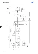
Figure 9.1:
Block diagram of V/f scale control
Summary of Contents for CFW500 V1.8X
Page 2: ......
Page 4: ......
Page 8: ...Contents...
Page 34: ...General Information 2 4 CFW500...
Page 38: ...About the CFW500 3 4 CFW500 3...
Page 42: ...HMI and Basic Programming 4 4 CFW500 4...
Page 52: ...Programming Basic Instructions 5 10 CFW500 5...
Page 56: ...Identification of the Inverter Model and Accessories 6 4 CFW500 6...
Page 76: ...Available Motor Control Types 8 4 CFW500 8...
Page 84: ...V f Scalar Control 9 8 CFW500 9...
Page 170: ...Communication 17 8 CFW500 17...

