


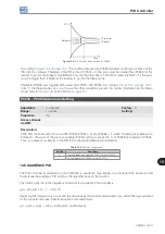


PID Controller
13-6 | CFW500
13
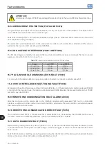
Table 13.1:
Setting of parameters for the example presented
Parameter
Description
P0203 = 1
Enables the PID controller via AI1 input (feedback).
P0205 = 40
Main display parameter selection (Process Variable).
P0206 = 41
Secondary display parameter selection (PID Setpoint).
P0207 = 2
Bar parameter selection (Motor Speed).
P0208 = 660
Reference scale factor.
P0209 = 0
Reference engineering unit: none.
P0213 = 660
Bar full scale.
P0210 = 1
Reference indication form: wxy.z.
P0220 = 1
Selection of LOC/REM source: operation in Remote condition.
P0222 = 0
Selection of REM reference: HMI.
P0226 = 0
Selection of remote direction of rotation: clockwise.
P0228 = 0
Selection of remote JOG source: inactive.
P0232 = 1.000
AI1 input gain.
P0233 = 1
AI1 input signal: 4 to 20 mA.
P0234 = 0.00 %
AI1 input offset.
P0235 = 0.15 s
AI1 input filter.
P0230 = 1
Dead zone (active).
P0536 = 1
P0525 automatic setting: active.
P0227 = 1
Selection of remote Run/Stop (DIx).
P0263 = 1
DI1 input function: Run/Stop.
P0265 = 22
DI3 input function: PID Manual/Automatic.
P0266 = 2
DI4 input function: General Enable.
P0527 = 0
PID controller action: direct.
P0528 = 250
PID VP indication scale.
P0529 = 1
PID VP indication form.
P0525 = 20.0
PID setpoint.
P0536 = 1
P0525 automatic setting: active.
P0520 = 1.000
PID proportional gain.
P0521 = 0.430
PID integral gain.
P0522 = 0.000
PID differential gain.
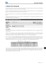
13.3 SLEEP MODE WITH PID
The Sleep mode is a useful resource to save on energy when the PID controller is used. In many applications with
PID controller, energy is wasted by keeping the motor spinning at the minimum speed when, for example, the
pressure or the level of a tank keeps rising.
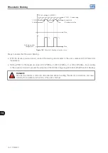
In order to enable the Sleep mode just program the frequency to sleep in parameter P0217 the following way:
P0133<P0217≤P0134. Besides that, parameter P0218 defines the time interval in which the input conditions in the
sleep mode, by P0217 and P0535, must remain stable. See the detailed description of P0535 below.
DANGER!
When in the Sleep mode, the motor can spin at any time considering the process conditions. If you
wish to handle the motor or execute any kind of maintenance, power down the inverter.
For further information on the configuration of the Sleep state, refer to
Section 11.3 SLEEP MODE on page 11-7
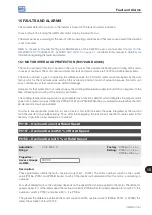
13.4 MONITORING MODE SCREEN
When the PID controller is used, the monitoring mode screen can be configured to show the main variables
numerically with or without engineering units.
One example of HMI with this configuration can be observed in
, where it is shown: the
process variable, the setpoint, both without engineering unit (with reference at 25.0 bars) and the motor speed
on the variable monitoring bar, according to the parameterization shown in
. For further
information refer to
Summary of Contents for CFW500 V1.8X
Page 2: ......
Page 4: ......
Page 8: ...Contents...
Page 34: ...General Information 2 4 CFW500...
Page 38: ...About the CFW500 3 4 CFW500 3...
Page 42: ...HMI and Basic Programming 4 4 CFW500 4...
Page 52: ...Programming Basic Instructions 5 10 CFW500 5...
Page 56: ...Identification of the Inverter Model and Accessories 6 4 CFW500 6...
Page 76: ...Available Motor Control Types 8 4 CFW500 8...
Page 84: ...V f Scalar Control 9 8 CFW500 9...
Page 170: ...Communication 17 8 CFW500 17...