


Digital and Analog Inputs and Outputs
CFW500 | 12-1
12
12 DIGITAL AND ANALOG INPUTS AND OUTPUTS
This section presents the parameters to configure the CFW500 inputs and outputs. This configuration depends
on the plug-in module, as per
.
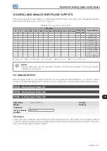
Table 12.1:
I/O configurations of the CFW500
Functions
Plug-in Module
DI
AI
AO
DOR
DOT
USB
CAN RS-232 RS-485 Profibus Ethernet
Sup
10 V
Sup
24 V
4
1
1
1
1
-
-
-
1
-
-
1
1
CFW500-IOS
8
1
1
1
4
-
-
-
1
-
-
1
1
CFW500-IOD
6
3
2
1
3
-
-
-
1
-
-
1
1
CFW500-IOAD
5
1
1
4
1
-
-
-
1
-
-
1
1
CFW500-IOR
4
1
1
1
1
1
-
-
1
-
-
1
1
CFW500-CUSB
2
1
1
1
1
-
1
-
1
-
-
1
1
CFW500-CCAN
2
1
1
1
1
-
-
1
1
-
-
-
1
CFW500-CRS232
4
2
1
2
1
-
-
-
2
-
-
1
1
CFW500-CRS485
2
1
1
1
1
-
-
-
1
1
-
-
1
CFW500-CPDP
2
1
1
1
1
-
-
-
1
-
1
-
1
CFW500-CETH-IP
CFW500-CEMB-TCP
CFW500-CEPN-IO
DI
– Digital Input
DOR
– Relay Digital Output
AI
– Analog Input
AO
– Analog Output
DOT
– Transistor Digital Output
NOTE!
CFW500 HMI shows just the parameters related to the resources available in the plug-in module
connected to the product.
12.1 ANALOG INPUTS
With the analog inputs, it is possible, for instance, to use an external speed reference or to connect a sensor
in order to measure temperature (PTC). Details for those configurations are described in the parameters below.
P0018 – Analog Input Value AI1
P0019 – Analog Input Value AI2
P0020 – Analog Input Value AI3
Adjustable
Range:
-100.0 to 100.0 %
Factory
Setting:
Properties:
ro
Access Groups
via HMI:
READ, I/O
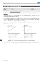
Description:
Those read-only parameters indicate the value of the analog inputs AI1, AI2 and AI3 in percentage of the full
scale. The indicated values are those obtained after the offset action and multiplication by the gain. Check the
description of parameters P0230 to P0245.
Summary of Contents for CFW500 V1.8X
Page 2: ......
Page 4: ......
Page 8: ...Contents...
Page 34: ...General Information 2 4 CFW500...
Page 38: ...About the CFW500 3 4 CFW500 3...
Page 42: ...HMI and Basic Programming 4 4 CFW500 4...
Page 52: ...Programming Basic Instructions 5 10 CFW500 5...
Page 56: ...Identification of the Inverter Model and Accessories 6 4 CFW500 6...
Page 76: ...Available Motor Control Types 8 4 CFW500 8...
Page 84: ...V f Scalar Control 9 8 CFW500 9...
Page 170: ...Communication 17 8 CFW500 17...