background image

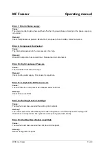
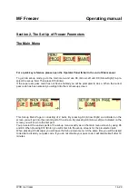
MF Freezer 

Operating manual 

WCB Ice Cream 


25-29 

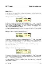
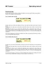
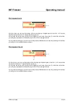
PLC Analog Input 1 


On this screen you can see that status of the first analog input in the PLC. The input range goes from 
4 to 20 mA and this range is converted in the PLC from 0 to 100 Percent. 
The analog in-read value is from the dasher load current transducer. 
 
If you press K5 (Escape) you will return to the previous Maintenance Screen. By pressing K10 (Enter) 
you will go to the next Maintenance screen: 


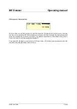
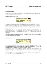
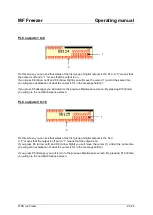
PLC Analog Input 2 


On this screen you can see that status of the second analog input in the PLC. The input range goes 
from 4 to 20 mA and this range is converted in the PLC from 0 to 100 Percent. 
This analog input is not used at present. 
 
If you press K5 (Escape) you will return to the previous Maintenance Screen. By pressing K10 (Enter) 
you will go to the next Maintenance screen: 
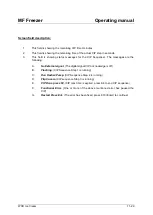


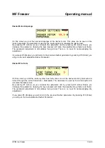
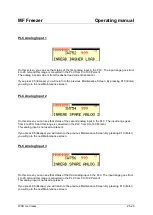
PLC Analog Input 3 


On this screen you can see that status of the third analog input in the PLC. The input range goes from 
4 to 20 mA and this range is converted in the PLC from 0 to 100 Percent. 
This analog input is not used at present. 
 
If you press K5 (Escape) you will return to the previous Maintenance Screen. By pressing K10 (Enter) 
you will go to the next Maintenance screen: 
Summary of Contents for MF

Page 1: ... Levels Section 1 The Operator Level The Main Menu Starting the pumps Starting the Dasher Starting the Compressor Starting the CIP The Mimic Screen Alarms Section 2 Set Up of Freezer Parameters CIP Parameters Pump Parameters Dasher Parameters Compressor Parameters Section 3 Maintenance Using the Check Screens Using Test Mode Operating panel folder ...

Page 2: ... if no other functions are running At the same time the green LED L4 will light up Pressing the key again will stop the CIP Sequence K5 Key No 5 Escape This button is used to acknowledge alarms as well as exiting the current displayed screen on the Operator panel K6 Key No 6 Left arrow This button is used to decrement setpoints on the production screens as well as moving the cursor in the menu and...

Page 3: ... On This LED will light up in green when power is applied to the operator terminal L7 Key Activated This LED will light up in green if a key is pressed on the operator terminal I1 Production Screen Auto Scroll Function Enabled This symbol will be displayed when the automatic page scroll function is enabled This function will automatically display the 4 production related pages on the screen The pa...

Page 4: ...ser Level When this level is activated by means of entering the correct pass code there is access to the Set Up menu where it is possible to adjust parameters related to the function of the freezer There is also access to the Maintenance Menu where it is possible to see the status and function of the In and outputs of the PLC When leaving the Set Up Manu the user will be prompted to disable the pa...

Page 5: ...he freezer This screen is normally displayed when an Emergency stop situation is cleared or exiting from production set up or Maintenance mode By pressing K6 Arrow Left or K9 Arrow Right it is possible to pre select production set up or maintenance functions Pre selection is indicated by the 3 squares on the screen changing from light to dark By pressing K10 Enter when on of the squares are pre se...

Page 6: ...n of the error see the alarm section If these alarms occur when the pumps are running the pumps will shut down L1 will turn off and the relevant alarm message will be displayed Screen field description 1 This field indicates the minimum capacity of the pumps It can be adjusted in the Set Up Menu 2 This is the pump speed setpoint in litres per hour 3 The bar graph is showing the pump speed setpoint...

Page 7: ...levant alarm message will be displayed If the Dasher load is exceeding the motor load warning threshold an alarm will be displayed and the back pressure valve will reduce its opening by 10 percent If the dasher load is exceeding the motor load shut down limit the dasher will stop and an alarm will be displayed Screen field description 1 This field indicates the current consumption of the dasher mo...

Page 8: ...s Supply Error 9 Compressor Overheated Error 10 High Condenser Pressure Error 11 Compressor Oil Pressure Low For a closer description of the error see the alarm section If these alarms occur when the compressor is running it will shut down L3 will turn off and the relevant alarm message will be displayed Screen field description 1 This is the opening of the backpressure valve in percent 2 The bar ...

Page 9: ...bol will change from light to dark 4 Dasher Motor Load Shows the actual load in percent 5 Product Pump When activated the symbol will change from light to dark 6 Pump Speed Shows the actual pump speed in percent 7 Hot Gas Valve When activated the symbol will change from light to dark 8 Opening of the Back Pressure Valve Shows the actual opening in percent 9 Liquid Valve When activated the symbol w...

Page 10: ...r Step 2 Running Dasher and Pumps Step 3 Flipping Pump Covers The duration of the steps can be adjusted in the Set Up Menu in the Sub Menu CIP When step 3 is finished the sequencer will do the steps again until CIP maximum time runs out or CIP is terminated by pressing K4 The CIP Sequencer can be controlled from an external CIP plant by using the Digital Input CIP Acknowledge see the electrical di...

Page 11: ...quencer The messages are the following A No External signal The digital signal CIP Acknowledge is off B Flushing CIP Sequence Step 1 is running C Run Dasher Pump CIP Sequence Step 2 is running D Flip Covers CIP sequence Step 3 is running E CIP Done press F4 CIP max time is expired press K4 to end CIP sequence F Functional Error One or more of the above mentioned error has paused the CIP G Restart ...

Page 12: ...t or by hand Remedy Remove overload short circuit condition and turn on the circuit breaker again Error 2 Breaker Compressor Tripped Cause The circuit breaker protecting the compressor motor has switched off by an overload short circuit or by hand Remedy Remove overload short circuit condition and turn on the circuit breaker again Error 3 Breaker Pump Drive Tripped Cause The circuit breaker protec...

Page 13: ...ndenser Pressure Cause The Condenser Pressure is too high Remedy Check cooling water supply Check water temperature Error 11 Compressor Oil Pressure Low Cause The Oil Pressure in compressor has dropped below safe limit Remedy Check Oil level refill Oil Error 13 Warning Dasher Load High Cause The Dasher Load has exceeded the warning limit setpoint Remedy The control system will automatically reduce...

Page 14: ...t into the main set up screen This Set up Main Page is consisting of 2 parts By pressing K9 Arrow Right as indicated on the screen you will get into the second part of the screen By pressing K6 Arrow Left as indicated on the screen you will return to the first part You pre select the various parts of the set up menu exactly as on the main menu screen by using K6 and K9 When pressing K10 Enter you ...

Page 15: ...On this screen you set the step 2 time for the CIP sequencer By pressing K7 Arrow up you increase the time and by pressing K8 Arrow Down you decrease the time Keeping the keys pressed will make the adjustments go faster and faster The setpoint adjustment is immediately being stored There Is no need for acknowledging the adjustment If you press K5 Escape you will return to CIP Step 1 time By pressi...

Page 16: ... time and by pressing K8 Arrow Down you decrease the time Keeping the keys pressed will make the adjustments go faster and faster The setpoint adjustment is immediately being stored There is no need for acknowledging the adjustment If you press K5 Escape you will return to CIP Step 3 time K10 Enter will not work since the CIP max time is the last parameter in this sub menu ...

Page 17: ...here is no need for acknowledging the adjustment If you press K5 Escape you will return to the Main Set up Menu By pressing K10 Enter you will go to the next adjustable Pump Parameter Pump Calibration Max Capacity On this screen you set the pump capacity in litres per hour when the pumps are running at maximum speed As the pump rotors wear down you may have to adjust this value in order to obtain ...

Page 18: ...l make the adjustments go faster and faster The parameter adjustment is immediately being stored There is no need for acknowledging the adjustment If you press K5 Escape you will return to the Main Set up Menu By pressing K10 Enter you will go to the next adjustable Dasher Parameter Dasher Max Load On this screen you set the maximum allowable load of the dasher When the dasher is running the contr...

Page 19: ...n to the previous Dasher parameter by pressing K10 Enter you will go to the next adjustable Dasher Parameter Dasher Wire Turns On this screen you tell the control system how many times one of the dasher motors power wired is turned through the current transducer Nameplate The parameter is used by the control system to calculate the dasher load By pressing K7 Arrow up you increase the parameter and...

Page 20: ...stem to calculate the dasher load By pressing K7 Arrow up you increase the parameter and by pressing K8 Arrow Down you decrease the parameter Keeping the keys pressed will make the adjustments go faster and faster The parameter adjustment is immediately being stored There is no need for acknowledging the adjustment If you press K5 Escape you will return to the previous Dasher parameter K10 Enter w...

Page 21: ...e that the evaporator is emptied for Halo Carbon This parameter sets the stop delay By pressing K7 Arrow up you increase the parameter and by pressing K8 Arrow Down you decrease the parameter Keeping the keys pressed will make the adjustments go faster and faster The parameter adjustment is immediately being stored There is no need for acknowledging the adjustment If you press K5 Escape you will r...

Page 22: ... correct pass code has been entered you will get into the first of the maintenance screens You can access the Maintenance screen even when the freezer is running PLC Inputs 1 to 8 On this screen you can see that status of the first group of digital inputs in the PLC A 0 means that the input is off and a 1 means that the input is on If you press K6 Arrow Left and K9 Arrow Right you will move the cu...

Page 23: ...cape you will return to the previous Maintenance screen By pressing K10 Enter you will go to the next Maintenance screen PLC Inputs 17 to 24 On this screen you can see that status of the third group of digital inputs in the PLC A 0 means that the input is off and a 1 means that the input is on If you press K6 Arrow Left and K9 Arrow Right you will move the cursor 1 and at the same time you will ge...

Page 24: ...cape you will return to the previous Maintenance screen By pressing K10 Enter you will go to the next Maintenance screen PLC outputs 9 to 16 On this screen you can see that status of the first group of digital outputs in the PLC A 0 means that the output is off and a 1 means that the output is on If you press K6 Arrow Left and K9 Arrow Right you will move the cursor 1 and at the same time you will...

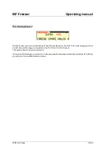
Page 25: ...at status of the second analog input in the PLC The input range goes from 4 to 20 mA and this range is converted in the PLC from 0 to 100 Percent This analog input is not used at present If you press K5 Escape you will return to the previous Maintenance Screen By pressing K10 Enter you will go to the next Maintenance screen PLC Analog Input 3 On this screen you can see that status of the third ana...

Page 26: ...the third fourth input in the PLC The input range goes from 4 to 20 mA and this range is converted in the PLC from 0 to 100 Percent This analog input is not used at present If you press K5 Escape you will return to the previous Maintenance Screen By pressing K10 Enter you will go to the next Maintenance screen ...

Page 27: ... to the previous Maintenance Screen By pressing K10 Enter you will go to the next Maintenance screen PLC Analog Output 2 On this screen you can see the status of the second analog output in the PLC The output range goes from 0 to 100 Percent which is converted in the PLC s analog output module to 4 to 20 mA This analog output is controlling the opening of the freezers backpressure valve If you pre...

Page 28: ...the status of the digital and analog outputs If you press K6 Arrow Left and K9 Arrow Right you will move the cursor 1 and at the same time you will get an explanation of what the output is for in the message field 2 If you press K7 Arrow Up you will change the status of the digital output from off to on If you press K8 Arrow Down you will change the status from On to Off If you want to change an a...

Reviews: