


80
CHAPTER 7
•
CHANNELS-ALERTS-ZONES
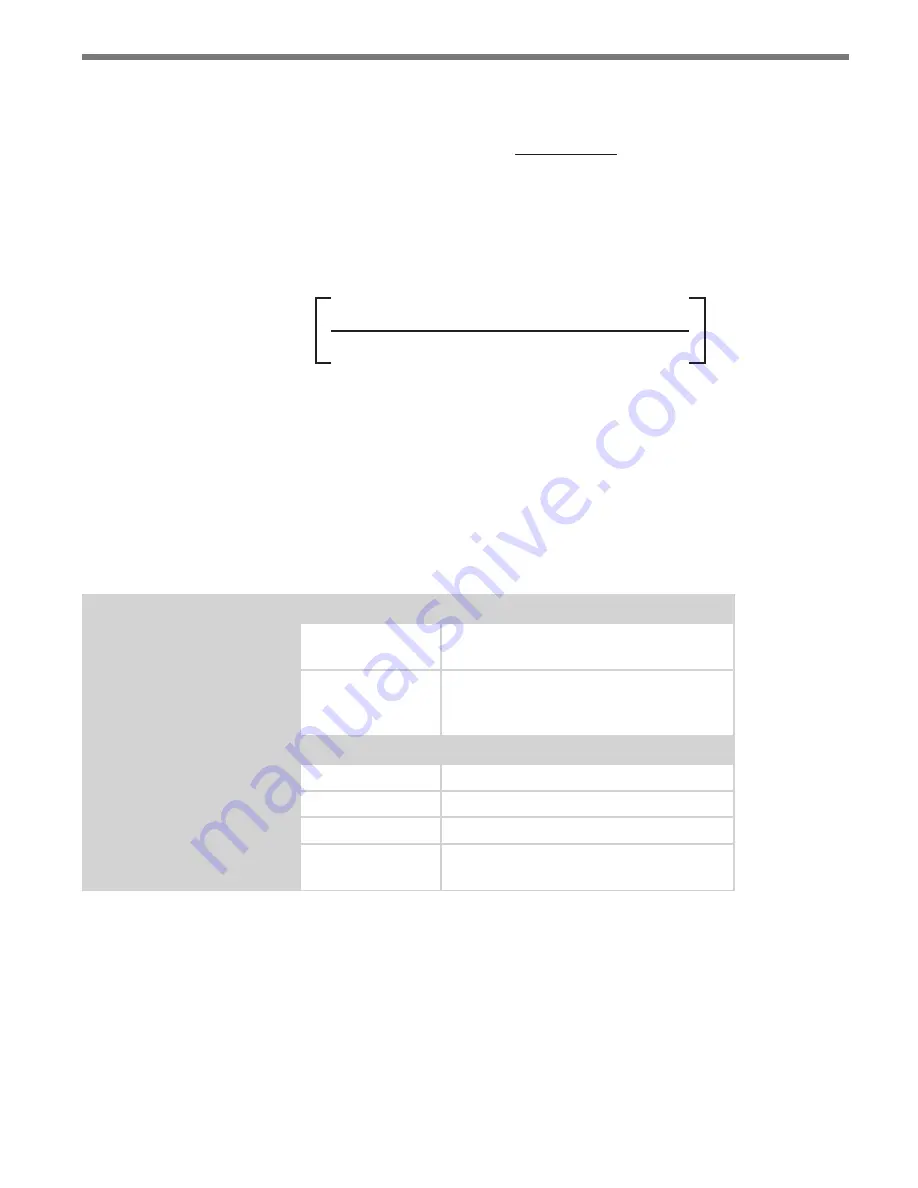
way between vehicles, this can be written as show in Figure 7.23.
%Utilization
Time Headway
Required
Flow Rate
%Utilization
Ideal
Flow Rate
=
x
=
Figure 7.23 – Equation for Dynamic Density Vehicle Count Threshold
Consequently, the Dynamic Density Count Requirement (DDCR) calculated by the Dy-
namic Density filter is computed as shown in Figure 7.24.
Time Headway x Instantaneous Mean Speed in Zone
%Utilization x Lane Tuning Factor x Zone Size
Dynamic Density
Count Requirement
(DDCR)
= Round
Figure 7.24 – Dynamic Density Count Requirement Equation
If the number of qualified detections is equal to or greater than the DDCR, then the Dy-
namic Density requirement has been satisfied and the zone output will be activated.
Table 7.1 below reviews the components of the Dynamic Density filter. The number of
qualified detections and their average speed is detected by the sensor. Then based upon
values of Zone Size, % Utilization, Tuning Factor, and headway parameters entered by the
user, the DDCR will be calculated and the zone output determined.
Component
Description
Detected by the Sensor
Qualified Count
The number of vehicles that meet a
zone’s range, speed and ETA filters.
Speed
The average speed of all qualified detec-
tions in the specified zone, as calculated
by the sensor (ft per second).
Entered by the User
Zone Size
The length of the specified zone (ft.).
%Utilization
Specified by the user (%).
Tuning Factor
Specified by the user.
Headway
Specified by the user (seconds per ve-
hicle).
Table 7.1 – Description of Dynamic Density Equation
Click in the display area beneath the Dynamic Density label to edit the Dynamic Density
filter (see Figure 7.25).


