background image


CHAPTER 8 

•  VERIFY CHANNELS-ALERTS-ZONES 

87

Note

In Figure 8.5 the dashed, gray line near the top of the zone is used to indicate the 
location of the discovery range threshold for this priority channel. Vehicles first dis-
covered before the discovery range threshold will be highlighted when viewing at the 
Level 1 alert and will also have a priority level of one when shown on the roadway. 
Vehicles first discovered after the discovery range threshold will be highlighted when 
viewing at the Level 2 alert and will also have a priority level of two when shown on 
the roadway.

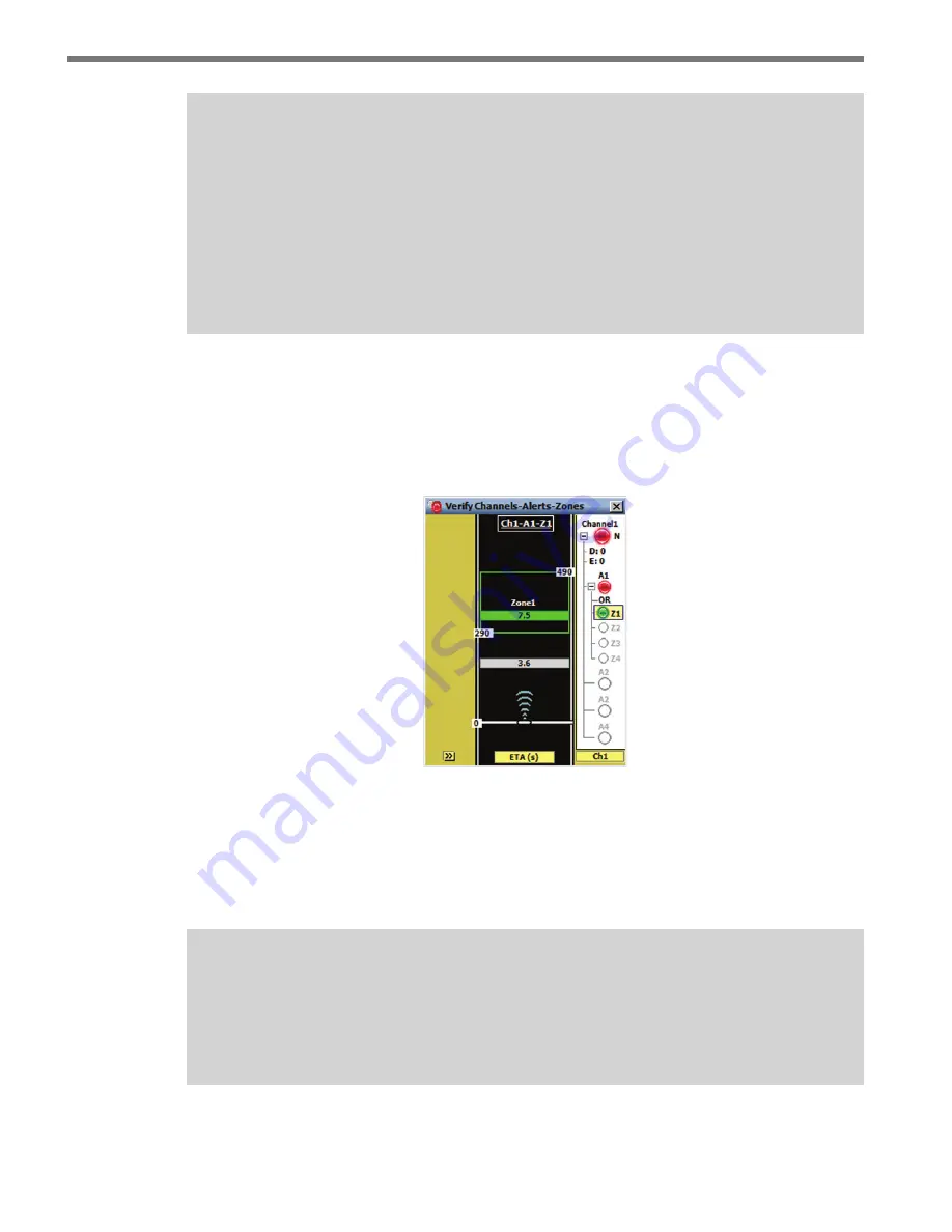
Simple channels (annotated with an S) show only the channel output in the right-side bar, 

and priority channels (annotated with a P) go one layer deeper to the alert level. Because a 

priority channel only has one zone for each alert, only the alert level is shown.  The normal 

channel (annotated with an N) and latched channel (L) go further down to the zone level 

(see Figure 8.6).

Figure 8.6 – Individual Channel View (Normal Channel)

A zone output is activated when its detection qualification filters are satisfied; an alert out-

put is activated when the associated zone outputs fulfill the alert’s logic filter; and a channel 

output is activated when the associated alert outputs (and related delay and extend settings) 

fulfill the channel’s requirements.

Note

Only channel outputs are reported to contact closure devices. While they are reported 
to SSMA, zone and alert outputs are not directly associated with any contact closure 
outputs.

The channel name is displayed above the channel LED. Latched channels display an L 

Summary of Contents for smartsensor advance

Page 1: ...SmartSensor Advance USER GUIDE...

Page 2: ...SmartSensor Advance USER GUIDE www wavetronix com 78 East 1700 South Provo Utah 84606 801 734 7200...

Page 3: ...ch state that operation is subject to the following two conditions 1 this device may not cause harmful interference and 2 this device must accept any interference received including interference that...

Page 4: ...ay 17 Apply ing Silicon Dielectric Compound 19 Connecting the Smart Sensor 6 conductor Cable 20 Grounding the Sensor 21 Chapter 3 Connecting Power and Surge Protection 23 Mounting the Backplate 24 Con...

Page 5: ...munications 101 Configuring Data Push Parameters 101 Chapter 11 Templates 105 Creating a Channel Template 106 Importing a Channel Template 106 Copying Pasting Channels Alerts and Zones 108 Chapter 12...

Page 6: ...n SmartSensor Advance Extended Range allows you to prioritize dilemma zone protection based upon the discov ery range of trucks and passenger cars SmartSensor Advance and SmartSensor Advance Extended...

Page 7: ...uctor cable SmartSensor Advance preassembled backplate SmartSensor Manager Advance SSMA software SmartSensor Advance User Guide SmartSensor Advance Quick reference Guides Check the packing slip for ac...

Page 8: ...and speeds above 35 mph 56 kph are generally considered unsafe for passenger vehicles For truck signal priority arrival times between 2 5 and 7 5 seconds ranges from 100 to 900 ft 30 5 to 274 3 m and...

Page 9: ...The sensor can detect incoming or outgoing traffic and filters out the opposite direction traffic Usually the sensor is used to detect incoming traffic With SmartSensor Advance Extended Range incoming...

Page 10: ...ptions see Figure I 1 1 On a vertical pole The preferred mounting location for the SmartSensor Advance or SmartSensor Advance Extended Range is often a vertical pole near the stop bar Verti cal poles...

Page 11: ...een time is so short that vehicles in the queue clearance zone do not start moving before the minimum green timer expires The SmartSensor Advance or SmartSensor Advance Extended Range can also be moun...

Page 12: ......

Page 13: ......

Page 14: ...Part 1 Installing the SmartSensor Advance Chapter 1 Installing the SmartSensor Advance Chapter 2 Connecting Power and Surge Protection...

Page 15: ......

Page 16: ...cess including how to attach the sensor to the pole and how to correctly align the sensor Warning Caution should be used when installing any sensor on or around active roadways Serious injury can res...

Page 17: ...sion Attaching the Mount Bracket to the Pole Before attaching the mount bracket to the pole first make sure that your cables are long enough to support the sensor height and the distance from the sens...

Page 18: ...nd pan ning it to the left or right as necessary see Figure 1 3 The target location is typically between 30 and 80 ft 9 1 and 24 4 m upstream from the sensor in the center of the lanes of interest See...

Page 19: ...Height Offset Target Distance Figure 1 3 Pointing the Sensor 2 Roll the sensor using the backplate while keeping it pointed at the target location to align the elliptical beam If the sensor is mounte...

Page 20: ...t If the sensor is mounted near the outside edge of the curved road you may be able to bisect the curve with little or no roll If the road curves dramatically you may need to reduce the down tilt of t...

Page 21: ...6 Sensor 6 conductor Cable Connector To avoid undue movement from the wind strap the 6 conductor cable to the pole or run it through a conduit but leave a small amount of slack at the top of the cabl...

Page 22: ...Sensor Advance must now be grounded 1 Connect a grounding wire to the grounding lug on the bottom of the sensor see Figure 1 5 2 Connect the other end of the grounding wire to the earth ground for the...

Page 23: ......

Page 24: ...de power and surge protection to the intersection preassembled backplate located in the main traffic cabinet The intersection preassembled backplate is 11 in 28 cm wide and 11 5 in 29 2 cm high Also a...

Page 25: ...eps to mount the backplate in the traffic cabinet 1 Locate the area planned for mounting the backplate The backplate can usually be mounted on the side panel of a NEMA style cabinet 2 Attach the backp...

Page 26: ...Connect a neutral wire usually a white wire to the bottom side of the terminal block labeled N for neutral 2 Connect a ground wire usually a green wire to the bottom of the terminal block la beled G...

Page 27: ...tion include Click 201 202 204 AC to DC converter A Click 201 provides 1 A of power and is capable of powering a single sensor a Click 202 provides 2 A and can power two sen sors a Click 204 provides...

Page 28: ...4 To enable or disable DC power to the backplate press the main circuit breaker left side of upper DIN rail to enable or disable DC power to an individual sensor press the individual circuit breaker l...

Page 29: ...ection and so there is no need to use a pole mount box for surge protection on the sensor side of the cable However it is strongly recommended that the sensor be connected to a surge protection device...

Page 30: ...enables a multi drop shared communication bus between all sensors connected to the backplate This allows control of all Advance sensors rack cards and other connected Click devices The remaining two...

Page 31: ...SAdvance 1 S Port A Port C Port B Port D Port A Port C Port B Port D Figure 2 7 Click 222 Ports A B C and D Terminating the 6 conductor Cables The SmartSensor Advance will receive power once each Sma...

Page 32: ...ver into the square slot and rocking it forward The plug in terminals will automatically complete the electrical connection There is no need to manually strip the insulation on the end of each wire Th...

Page 33: ...he contact closure cards In some cases sev eral contact closure cards can be daisy chained together However if you are using the Click 172 174 cards the chain should not be connected until each card h...

Page 34: ...Advance Chapter 4 Communication Chapter 5 Sensor Settings Chapter 6 Sensor Configuration Chapter 7 Channels Alerts Zones Chapter 8 Verify Channels Alerts Zones Chapter 9 Setup Output Communications C...

Page 35: ......

Page 36: ...Sensor Advance SS200 This part of the user guide is designed to illustrate SSMA functionality and describes the basic steps and procedures needed to correctly configure the SmartSensor Advance Install...

Page 37: ...ick the SmartSensor icon This will bring up drop down menus allowing you to select a product by name or part number 4 Select SmartSensor Advance and a list of links will appear 5 Select the SmartSenso...

Page 38: ...reader program i e Adobe Acrobat Reader is required to view the release notes 11 Click Finish to complete the setup process Installing SSMA on a Handheld Computer If you would like to run SSMA on a ha...

Page 39: ...l become available 3 Click the Pocket PC checkbox and then the Next button to install SSMA on a con nected Pocket PC device see Figure 3 4 If both the Computer and Pocket PC boxes are checked the setu...

Page 40: ...figure the sensors to the roadway Launch SSMA by either clicking on the icon that was placed on your desktop or clicking the icon found in the Start menu The SSMA main screen shown in Figure 4 1 will...

Page 41: ...tab lished After the first connection is made to the SmartSensor Advance the SSMA software will save the connection settings that were used Click the lightning bolt icon on the right side of the commu...

Page 42: ...connect to the first sensor it finds If you have multi ple sensors and want to be able to connect to each one use the Multi drop Network tab see Multi drop Network section below Internet Connection 1...

Page 43: ...ensor Virtual Connection A virtual connection allows you to use the SSMA software without being connected to an actual sensor Making a virtual connection can be useful for the following reasons To vie...

Page 44: ...ing glass icon and entering a file name When you create a new virtual sensor you will need to complete two steps First you need to open the new file see Figure 4 5 Figure 4 5 Open New File Second you...

Page 45: ...e configuration settings that you created After the file is successfully backed up the virtual sensor file will change to a sensor setup file and can be restored to any sensor in the field Selecting a...

Page 46: ...call Wa vetronix Technical Support at 801 764 0277 for assistance Multi drop Network The SSMA software automatically discovers the multi drop ID of sensors over the selected port normally you will au...

Page 47: ...at the bottom of the Communication page to add new con nection settings to the address book see Figure 4 10 Edits the selected device Adds a device to the Address Book Deletes a device from an Addres...

Page 48: ...ion Shows how long you have been connected Failures Shows the amount of failures during the connection the percentage rate of failure and a link to the Communication Error Log Check Hardware After you...

Page 49: ...rors stored in the sensor s memory buffer If you are having trouble connecting using the error log may be helpful in the troubleshooting process If you continue having trouble save the error log file...

Page 50: ...are and the sensor Once the Version Control screen appears you can do one of the following 1 Upgrade the sensor s embedded software by clicking the INSTALL UPGRADE but ton 2 Click the close button and...

Page 51: ...version 2 0 and later supports 128 zones 8 channels 4 alerts per channel and 4 zones per alert During the firmware upgrade process SSMA will determine if the sensor is running any previous versions If...

Page 52: ...s link on the main menu to change and save settings on the sensor The Sensor Settings window contains General and Communication tabs see Figure 5 1 Figure 5 1 Sensor Settings Screen General Tab The Ge...

Page 53: ...nce devices in close proximity will require each one to be set to a different RF channel Similarly using multiple SmartSensor Advance Extended Range devices in close proximity will re quire each one t...

Page 54: ...as the data bus and is normally left at 9600 bps in order to match the default setting on a Click 112 114 card If you change this baud rate on the sensor you will also need to change it on the rack c...

Page 55: ......

Page 56: ...tallation details an automatic configuration feature and manual configuration tools see Figure 6 1 Figure 6 1 Sensor Configuration Screen Click the lighting bolt icon on the bottom right corner of the...

Page 57: ...alues and the Cancel button closes the screen without saving changes to the sensor Changing the Traffic Direction The SmartSensor Advance can be configured to detect traffic moving towards or away fro...

Page 58: ...e measurements to range measurements that are relative to the roadway s frame of reference The sensor position is also used in the Beam Alignment tool see Tools Note The sensor s range is updated when...

Page 59: ...to begin the auto configuration process The playing time will be shown in the top left corner of the screen After approximately three minutes trackers sensor detec tions will begin to appear on the r...

Page 60: ...l Radar Adjustment Screen for Advance left and Advance Extended Range right Note The ranges displayed in the Manual Radar Adjustment window will depend upon whether you have SmartSensor Advance or Sma...

Page 61: ...e power button will turn red see Figure 6 8 but once the sensor has rebooted it will go back to green again Figure 6 8 Red Button During Reboot Editing Sensitivity If missed detections are consistentl...

Page 62: ...or to signal an actuated traffic controller based on both detections In cases of double detections the thresholds will not need to be increased Follow the steps below to adjust the sensitivity 1 Deter...

Page 63: ...s 6 After adjusting the sensitivity click the Enter button to apply the adjustment 7 Click the OK button to accept the modifications and close the Edit Sensitivity win dow click the Undo button to ret...

Page 64: ...ing the PGA The Programmable Gain Amplifier PGA allows you to change the radar sensitivity for the entire approach see Figure 6 11 Note Consult with Wavetronix Technical Services before changing the P...

Page 65: ......

Page 66: ...ts and zones set up output communications and import create a template see Figure 7 1 Figure 7 1 Channels Alerts Zones Screen This chapter will explain the different types of channels and how they are...

Page 67: ...nal types of channels Normal and Latched see Figure 7 2 Figure 7 2 Channel Configuration The channel configuration is read from the sensor the first time that the CAZ job is se lected Due to the amoun...

Page 68: ...the size of the zone by either clicking and dragging the zone arrows anywhere along the road way or by using the up down arrows in the Range feet field You can set the Speed and ETA settings by first...

Page 69: ...high end 8 Name the channel Advance and click OK to save the channel settings Follow the steps below to configure the QReduce channel 1 Click the second tab on the top of the Setup Channels Alerts Zon...

Page 70: ...of protection Note Priority channels are only available with SmartSensor Advance Extended Range The extended range of the sensor is best matched to Distinguish between large vehicles trucks and buses...

Page 71: ...er For the queue clearance zone a 1 0 passage time is added to the maximum time headway between two vehicles occupying the zone at the same time to determine the maximum al lowable time headway When t...

Page 72: ...other applications than truck priority For example you could require that a vehicle be discovered at a certain range using the discovery range threshold and that it travels to a down stream zone sever...

Page 73: ...s eight channels with the selected tab showing the channel number and channel name the middle portion of the screen contains alert configuration parameters and the lower portion of the screen contain...

Page 74: ...attempt to save an invalid channel configuration the following message is displayed see Figure 7 10 Figure 7 10 Invalid Channel Configuration Latched Channel Latched channels consist of two alerts ON...

Page 75: ...d 2 will be used as the ON and OFF alerts respectively alerts 3 and 4 will be disabled Delay The channel delay is used to ignore alert outputs that are shorter than the specified delay time see Figure...

Page 76: ...e ON state The latch timer can also be used to generate a latched output of specified duration This timed output can be achieved by defining the OFF alert to have a configuration that is not likely es...

Page 77: ...ng specifies the Boolean logic operation to be applied to the alert s zone outputs The available options are OR and AND If OR logic is selected the alert will turn ON if one or more zones have active...

Page 78: ...range Click in the zone range display next to the range label to open the zone range editor see Figure 7 17 Figure 7 17 Zone Range Editor To add enable a zone drag the desired zone icon from the zone...

Page 79: ...bel to enable the speed filter only speeds within the range will activate zone outputs uncheck the box to disable the speed filter all speeds will activate zone outputs Edit the min and max values in...

Page 80: ...mic Density is a type of vehicle platoon detection that activates a zone s output when the number of qualified detections within a zone equals or exceeds a density requirement The following equations...

Page 81: ...activated Table 7 1 below reviews the components of the Dynamic Density filter The number of qualified detections and their average speed is detected by the sensor Then based upon values of Zone Size...

Page 82: ...seconds and the maximum headway value is 10 0 seconds Utilization refers to the ratio of observed flow rate to ideal flow rate It is a measure used to describe traffic efficiency in terms of the idea...

Page 83: ......

Page 84: ...Tracker Highlighting 8 The Verify Channels Alerts Zones screen contains both configuration and detection infor mation see Figure 8 1 Figure 8 1 Verify CAZ Screen for Advance left and Advance Extended...

Page 85: ...martSensor Advance is functioning correctly Note Simple channels are shown on the right side bar with the letter S next to the chan nel LED latched channels are shown with the letter L Right Sidebar T...

Page 86: ...Channels The All Channels view shows an LED for each of the SmartSensor Advance s eight channel outputs The channel outputs are transmitted to a contact closure device which in turn generates an appro...

Page 87: ...hannel summary screen shows the channel type delay and extend settings and all enabled alerts for that channel Individual Channel The individual channel view allows you to see the CAZ elements defined...

Page 88: ...ated with a P go one layer deeper to the alert level Because a priority channel only has one zone for each alert only the alert level is shown The normal channel annotated with an N and latched channe...

Page 89: ...lert Summary screen The top of the Alert Summary screen shows the channel that the alert belongs to The rest of the screen shows the logic applied to the alert which zones are enabled and which zones...

Page 90: ...an alert is selected the corresponding zones will appear on the roadway each with a unique color Figure 8 9 Alert LED Zone LED Each of the four available zones show a different color This color mappi...

Page 91: ...e met or NOT met if the zone out put is being inverted the corresponding zone LED is colored its corresponding zone color Figure 8 10 Zone Highlighting Note Tracker highlight behavior is determined by...

Page 92: ...tab for the current channel selected The stop bar icon represents placement of the sensor relative to the approach s stop bar A stop bar label showing the relative location of the stop bar will be dis...

Page 93: ...igit identification number 1 to 99999 to each tracker Qualified Count The two types of Qualified Count displays available are Qualified Count and Dynamic Density The data displayed on the trackers dep...

Page 94: ...d Count maximum the number in parentheses is preceded by a if the number of qualified detections is in between the Qualified Count minimum and maximum settings a 0 is displayed Figure 8 14 describes t...

Page 95: ...r of qualified detections divided by the DDCR see Figure 8 16 Detected Qualified Count Dynamic Density Threshold Displayed Text 2 4 02 050 4 4 04 100 6 4 06 150 Figure 8 15 Display Text for Dynamic De...

Page 96: ...ority Level is abbreviated P Level and Level respectively Any mode can be assigned to display on the left 1 middle 2 or right 3 side of the tracker display see Figure 8 17 and 8 18 A mode cannot be di...

Page 97: ...d dis covery range requirements it does at least meet the requirement for the currently displayed range speed ETA discovery range or priority level property Tracker Highlighting When a channel alert o...

Page 98: ...oes not meet ALL range speed and ETA requirements it does at least meet the requirement for the currently displayed range speed or ETA property The zone highlighting rules also apply to the correspond...

Page 99: ...ance of the Verify CAZ screen Scale View Shows a distance scale relative to the stop bar The sensor is always dis played at the bottom and is oriented to point towards the top of the screen Logging Vi...

Page 100: ...ration of the logging session is displayed on the Elapsed timer display Click the toggle switch to the OFF position to end a tracker logging session The tracker log file is an ASCII text file and can...

Page 101: ......

Page 102: ...a transfer instead of responding to data requests from another device The features located in the Setup Output Communica tion screen allow you to configure the data push parameters see Figure 9 1 Figu...

Page 103: ...e aware that in standard installations Port 1 is designated as the control bus For SS200V sensors the control bus is an RS 485 port usually connected to the bridge port of a Click 222 and is shared wi...

Page 104: ...duration in seconds The minimum output duration is the minimum amount of time that a channel output will be on even if the output conditions are removed The selected value should meet the timing requ...

Page 105: ......

Page 106: ...tools for simplifying frequently used or standardized chan nel configurations A channel template is a text file that contains all the CAZ configuration settings required to completely define a channe...

Page 107: ...e File Screen Importing a Channel Template The SSMA software contains pre defined channel templates that can be modified to meet your needs An existing channel template can be loaded into any of the S...

Page 108: ...tection range If this is the case a message will appear stat ing the number of configured zones that are invalid for the sensor s position relative to the stop bar and you will be prompted to accept t...

Page 109: ...e sensor s position or the channel can be configured in the software Changes that have not been written to FLASH memory will be lost the next time the sen sor reboots Copying Pasting Channels Alerts a...

Page 110: ...restore sensor settings visualize the sensor alignment and communicate with the sensor using a serial terminal see Figure 11 1 The Tools job varies depending on whether or not SSMA is connected to a...

Page 111: ...ight Once the proper file has been specified you can start the backup or restore operation Backing Up the Configuration Click the Back up Sensor Setup button to save the current configuration The Sele...

Page 112: ...ayed out and may not be selected for restoration Click OK to perform the backup process and save the new set tings to FLASH Click Cancel to return to the Backup Restore screen Note If the serial baud...

Page 113: ...sage will appear stating the number of configured zones that are invalid for the sensor s position relative to the stop bar and you will be prompted to accept the modified results of the restored conf...

Page 114: ...the Beam Alignment icon to start the Beam Alignment tool see Figure 11 9 This tool is used to help the person installing the sensor to visualize the invisible radar beam footprint based on the sensor...

Page 115: ...spot The target is depicted on the roadway view with cross hairs and a light green color Target Y The offset as shown in Figure 1 3 and Tables 1 1 and D 1 see Chapter 1 and Appendix D The Approach Wid...

Page 116: ...200 command in the Tx Transmit win dow located on the bottom of the Serial Terminal screen Each SS200 command must be terminated with a carriage return 0x0D which is accomplished by pressing the Retur...

Page 117: ...gh conduit or the sensors are being installed Note When used with SmartSensor Advance the rack cards should be configured to com municate at the default 9600 bps If you are having communication issues...

Page 118: ...you have selected All Rack Cards then the main menu LEDs of every card connected on the bus will begin flashing Channel Outputs Switch The Channel Outputs toggle switch and 1 16 checkboxes are used to...

Page 119: ......

Page 120: ...otocol Communication from the sen sor can be set up by the cards or by using SmartSensor Manager To connect and autobaud to the detector rack cards 1 Connect from the Click 222 RS 485 A port to a bus...

Page 121: ...485 port 3 Select Z4 Click 112 114 from the output format drop down list to set up commu nication with a Click 112 114 4 Click OK to save the communication changes 5 Verify that detections are registe...

Page 122: ...e rack Make sure the Settings switch is in the 3 position when plugged in Wait approximately 20 seconds 2 Move the Settings switch to the 1 position and after the auto baud is complete the current mod...

Page 123: ...hs greater than 200 ft 61 m Rack Card Dip Switch If you are seeing calls on the rack card LEDs but do NOT see them registering in your controller you may need to disable the rack card s pull up circui...

Page 124: ...ect a patch cable to the Click 222 RJ 11 jack for the sensor you want to get data from Connect the other end to either of the RJ 11 jacks on the faceplate of the Click 104 2 If you are using multiple...

Page 125: ...104 Configuration You can configure the Click 104 with Click Supervisor using the front panel menu or us ing the rotary switch Each configuration option allows you to change different parameters some...

Page 126: ...n Options If you have used the rotary switch to set the channel input mapping which is the only thing you can do with the rotary switch that mapping cannot be set or changed with the front panel menu...

Page 127: ......

Page 128: ...nt 13 Appendix A Cable Connector Definitions The connector end of the SmartSensor 6 conductor cable mates to the 8 pin connector on the SmartSensor Advance see Figure A 1 A B C D E F G H Figure A 1 Sm...

Page 129: ...are normally used for communication Follow the steps below to create a custom cable see Figure A 2 1 Slide the strain relief follower grommet and back shell over the cable 2 Strip the cable jacket and...

Page 130: ...mum cable lengths are longer Maximum Cable Length for Powering SS200V The following recommendations allow you to provide reliable power to the SmartSensor The SmartSensor cable s red and black wires p...

Page 131: ...m 6 conductor Cable Native RS 485 Native RS 485 1500 2000 ft 457 2 609 6 m 6 conductor Cable Native RS 485 NA 2000 2500 ft 609 6 762 m Alternate cable for power and communications Native RS 485 Nativ...

Page 132: ...patible with the length of the cable run The table below shows the cable length recommendations for wired communications see Table B 5 Baud Rate RS 232 RS 485 115 2 40 ft 12 2 m 300 ft 91 4 m 57 6 60...

Page 133: ...nates in a surge pro tection device However during demonstrations troubleshooting and certain other situ ations it is sometimes convenient to bypass surge protection and connect directly to a personal...

Page 134: ...ications and support USB com munications instead If your computer only supports USB communications you may want to use a Click serial to USB converter to make a direct connection Appendix D Target Rol...

Page 135: ...able D 1 Target Roll Angle Note If you would like to narrow the coverage of the sensor at far ranges consider reducing the target location by about 25 For example if your current target location is 40...

Page 136: ......

Reviews: