Broadband Analyzer/Generator
ANT-20/ANT-20E
A-6
Application Guide
A) To set the topology
⇒
Select the “Emulate” option in the “Port configuration” field to allow activation of signaling
emulation.
“Emulate” can only be selected if the physical layer is set to the same bit rate and mapping for
both generator and receiver; see D.
B) To enable signaling emulation
⇒
Check the “Signaling emulation” check box.
A check appears in the check box.
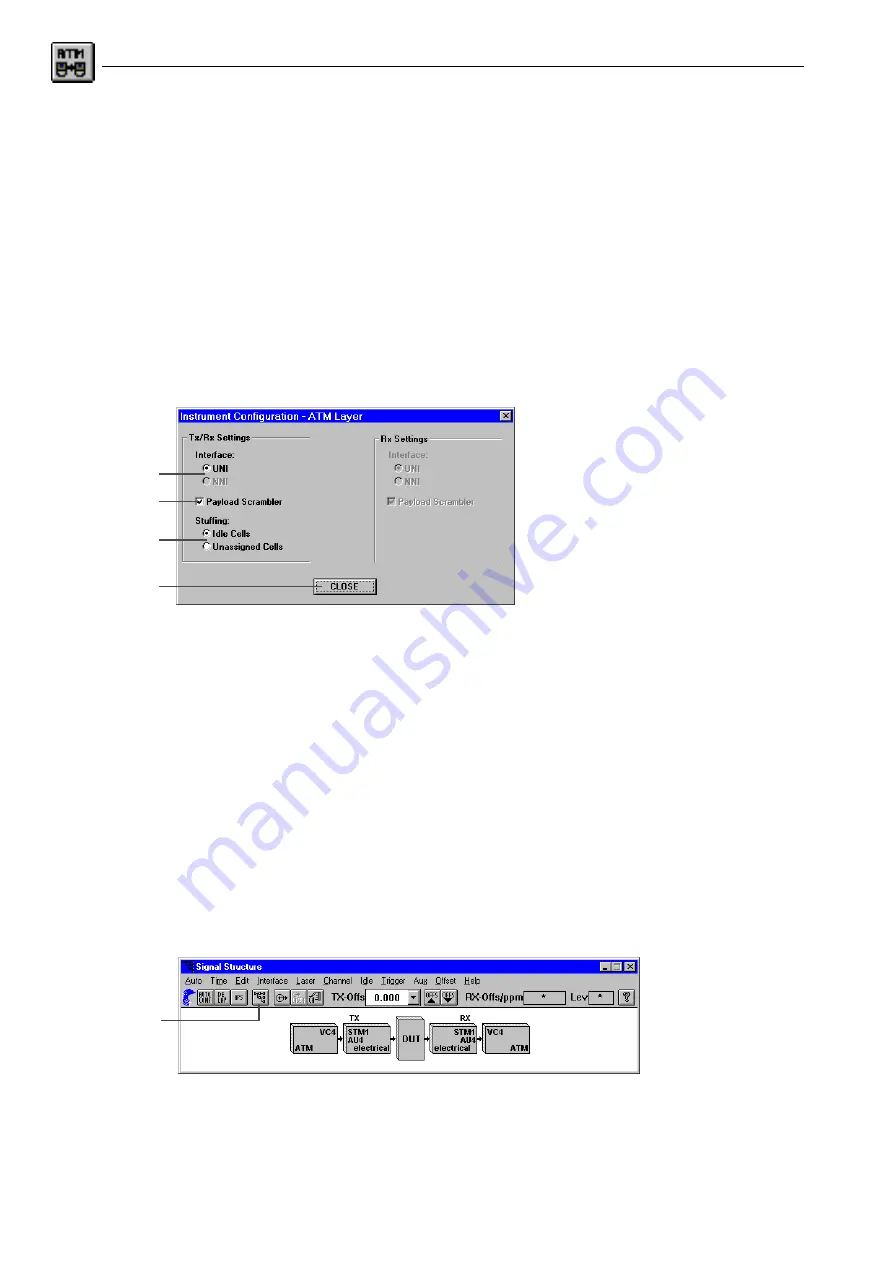
C) To configure the ATM layer
1. Click the “ATM” button.
The “Instrument Configuration - ATM Layer” dialog window opens.
Fig. A-8
The “Instrument Configuration - ATM Layer” sub dialog
2. Select the interface corresponding to the actual measurement connection of the instrument
by means of the “Interface” option buttons. If signaling is used, only the UNI interface type
for terminal equipment is available.
3. Check the “Payload Scrambler” check box if the test cell payload is to be scrambled.
4. Select the type of justification cells using the “Stuffing” option buttons:
– “Idle Cells” or “Unassigned Cells”.
5. Click the CLOSE button to confirm the configuration of the ATM layer; this returns you to the
“Instrument Configuration” dialog.
D) To configure the physical layer: VI “Signal Structure”
Example: STM-1, C-4 mapping
✓
The “Instrument Configuration” dialog is open.
⇒
Click the “PHYSICAL” button.
The VI “Signal Structure” opens.
Fig. A-9
The “Signal Structure” main window
2.
3.
4.
5.
1.
Summary of Contents for ANT-20
Page 8: ...Broadband Analyzer Generator ANT 20 ANT 20E vi Notes ...
Page 64: ...Broadband Analyzer Generator ANT 20 ANT 20E O 46 Operation Notes ...
Page 110: ...Broadband Analyzer Generator ANT 20 ANT 20E TB 16 Technical Background Notes ...
Page 126: ...Broadband Analyzer Generator ANT 20 ANT 20E iv Notes ...


