background image

AERCO ProtoNode FPC-N34 & FPC-N35 User Manual  

User Manual 


Page 

2

 of 

108


 AERCO International, Inc. 

 100 Oritani Dr. 

  Blauvelt, NY 10913  


OMM-0107_0B


03/07/2017


 Ph.: 800-526-0288  


GF-150 

OMM-0107 

GF-150 


Technical Support 

(Mon-Fri, 8am-5pm EST) 

1-800-526-0288 

Website: 

www.aerco.com


Certifications 


BTL MARK – BACNET TESTING LABORATORY  


LONMARK CERTIFICATION 

Thank you for purchasing the ProtoNode for AERCO products.  
 
Please call AERCO for Technical support of the ProtoNode product. 
 
SMC does not provide direct support.   If AERCO needs to escalate the concern, they will contact 
Sierra Monitor Corporation for assistance.  

DISCLAIMER


The information contained in this manual is subject to change without notice from AERCO 
International, Inc. AERCO makes no warranty of any kind with respect to this material, including, but 
not limited to, implied warranties of merchantability and fitness for a particular application. AERCO 
International is not liable for errors appearing in this manual, nor for incidental or consequential 
damages occurring in connection with the furnishing, performance, or use of these materials.   


The BTL Mark on ProtoNode FPC-N34 is a symbol that indicates that a 
product has passed a series of rigorous tests conducted by an 
independent laboratory which verifies that the product correctly 
implements the BACnet features claimed in the listing.  The mark is a 
symbol of a high-quality BACnet product.   
Go t

http://www.BACnetInternational.net/btl/

  for more information 

about the BACnet Testing Laboratory. Click here for 

BACnet PIC 

Statement


LonMark International is the recognized authority for certification, 
education, and promotion of interoperability standards for the benefit of 
manufacturers, integrators and end users. LonMark International has 
developed extensive product certification standards and tests to 
provide the integrator and user with confidence that products from 
multiple manufacturers utilizing LonMark devices work together. Sierra 
Monitor has more LonMark Certified gateways than any other gateway 
manufacturer, including the ProtoCessor, ProtoCarrier and ProtoNode 
for OEM applications and the full featured, configurable gateways. 

Summary of Contents for 64129

Page 1: ...9 AERCO LonWorks ProtoNode FPC N35 Part Number 64130 For interfacing with the following AERCO products AM Series C More Modulex ECS SmartPlate BMS BMSII ACS For interfacing with the following Building Automation Systems BACnet MS TP BACnet IP Modbus TCP IP Modbus RTU Metasys N2 LonWorks Latest Revision March 07 2017 This user manual applies only to ProtoNode Models FPC N34 P N 64129 and FPC N35 P ...

Page 2: ... incidental or consequential damages occurring in connection with the furnishing performance or use of these materials The BTL Mark on ProtoNode FPC N34 is a symbol that indicates that a product has passed a series of rigorous tests conducted by an independent laboratory which verifies that the product correctly implements the BACnet features claimed in the listing The mark is a symbol of a high q...

Page 3: ...s RTU FPC N34 Setting the Baud Rate for BAS Network 16 CHAPTER 3 Interfacing ProtoNode to Devices 17 3 1 ProtoNode FPC N34 and FPC N35 Showing Connection Ports 17 3 2 Device Connections to ProtoNode 18 3 2 1 Biasing the Modbus RS 485 Device Network 19 3 2 2 End of Line Termination Switch for the Modbus RS 485 Device Network 20 3 3 BACnet MS TP Modbus RTU or Metasys N2 FPC N34 Wiring Field Port to ...

Page 4: ...net MS TP BACnet IP Metasys N2 Modbus TCP IP and LonWorks 63 Appendix C 4 Modulex Modbus RTU Mappings to BACnet MS TP BACnet IP Metasys N2 Modbus TCP IP and LonWorks 63 Appendix C 5 ECS Modbus RTU Mappings to BACnet MS TP BACnet IP Metasys N2 Modbus TCP IP and LonWorks 64 Appendix C 6 ACS BMSII BMS Modbus RTU Mappings to BACnet MS TP BACnet IP Metasys N2 Modbus TCP IP and LonWorks 65 Appendix D Ei...

Page 5: ...10913 Page 5 of 108 GF 150 Ph 800 526 0288 03 07 2017 OMM 0107 GF 150 Appendix I 4 AM Status Parameters Table 100 Appendix I 5 Cascade Connection of AM Boiler with ProtoNode 101 Appendix J Reference 104 Appendix J 1 Specifications 104 Appendix J 2 Compliance with UL Regulations 104 Appendix K Limited 2 Year Warranty 107 ...

Page 6: ...A 2 5 1 6 BACnet MS TP or BACnet IP FPC N34 Set the BACnet Device Instance 2 5 2 7 Metasys N2 Modbus RTU or Modbus TCP IP FPC N34 Set the Node ID 2 5 3 8 BACnet MS TP or Modbus RTU FPC N34 Set the BAUD rate of the Field Protocol on DIP Switch Bank B 2 5 4 9 Connect ProtoNode s 6 pin RS 485 connector to the Modbus RS 485 network that is connected to each of the devices 3 2 10 Connect ProtoNode FPC ...

Page 7: ...them for BACnet 1 MS TP BACnet IP Metasys 2 N2 by JCI Modbus RTU Modbus TCP IP or LonWorks 3 It is not necessary to download any configuration files to support the required applications The ProtoNode is pre loaded with tested Profiles Configurations for the supported devices Figure 1 1 ProtoNode Connections to Devices 1 BACnet is a registered trademark of ASHRAE 2 Metasys is a registered trademark...

Page 8: ...ly controlled indirect systems Built in translation for BACnet IP BACnet MS TP LonWorks Metasys N2 and Modbus TCP Protocols Supports individual units and systems including AERCO s WHM and BST Select protocol and baud rate in the field using simple DIP switch selection Captures alarm and trend history for faster troubleshooting Non volatile memory retains point mappings and programs in the event of...

Page 9: ...municate to BST and WHM Modbus masters The AERCO SSD device is unique because it enables two Modbus masters to bi directionally communicate over RS 485 The AERCO SSD device is also specifically designed to support the BST WHM Automatic failover Feature While the BST WHM role can be transferred to another unit with a different Modbus address the SSD device operates at a fixed and constant Modbus ad...

Page 10: ...toNode FPC N34 FPC N35 User Manual CHAPTER 1 Introduction Page 10 of 108 AERCO International Inc 100 Oritani Dr Blauvelt NY 10913 OMM 0107_0B 03 07 2017 Ph 800 526 0288 GF 150 This Page Left Intentionally Blank ...

Page 11: ...its have the following 3 ports RS 485 Ethernet RS 485 ProtoNode FPC N35 units have the following 3 ports LonWorks Ethernet RS 485 2 2 Point Count Capacity and Registers per Device The total number of Modbus Registers presented by all of the devices attached to the ProtoNode cannot exceed Part number Total Registers FPC N34 0645 1 500 FPC N35 1051 1 500 Figure 2 2 Supported Point Count Capacity Dev...

Page 12: ... for each of the Devices attached to the ProtoNode Set Modbus Node ID for each of the devices attached to ProtoNode The Modbus Node ID s need to be uniquely assigned between 1 and 255 o The Modbus Node ID that is assigned for each device needs to be documented The Modbus Node ID s assigned are used for designating the Device Instance for BACnet IP and BACnet MS TP Section 2 5 2 The Metasys N2 and ...

Page 13: ... 2 4 2 Enabling Auto Discovery Not used on BST or WHM The S3 DIP switch is used to both enable Auto Discovery of known devices attached to the ProtoNode and to save the recently discovered configuration See the table in Figure below for the switch setting to enable Auto Discovery If the ProtoNode is being installed for the first time set S3 to the ON position to enable Auto Discovery Cycle the pow...

Page 14: ...elected again 7 If any profiles are present and not desired select them and click Remove 8 Select your desired profiles and click Add 9 Enter the Node ID or equipment address 10 Select the Current Profile of the equipment from the drop down box 11 Once your information is correct click on Submit or click Cancel and enter your information again 12 Repeat steps 8 to 11 to add more equipment profiles...

Page 15: ...hat was assigned in Section 2 3 2 The BACnet Device Instance can range from 1 to 4 194 303 For example Node_Offset value default 50 000 o Device 1 has a Modbus Node ID of 1 o Device 2 has a Modbus Node ID of 2 o Device 3 has a Modbus Node ID of 3 o Given that Device Instance Node_Offset Modbus Node_ID o Device Instance Device 1 50 000 1 50 001 o Device Instance Device 2 50 000 2 50 002 o Device In...

Page 16: ...2 5 4 BACnet MS TP or Modbus RTU FPC N34 Setting the Baud Rate for BAS Network B bank DIP switches B0 B3 can be used to set the Field baud rate of the ProtoNode to match the baud rate required by the Building Management System for BACnet MS TP or Modbus RTU The baud rate on ProtoNode for Metasys N2 is set for 9600 B bank DIP switches B0 B3 are disabled for Metasys N2 on ProtoNode FPC N34 B bank DI...

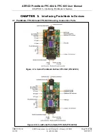
Page 17: ... International Inc 100 Oritani Dr Blauvelt NY 10913 Page 17 of 108 GF 150 Ph 800 526 0288 03 07 2017 CHAPTER 3 Interfacing ProtoNode to Devices 3 1 ProtoNode FPC N34 and FPC N35 Showing Connection Ports Figure 3 1a Serial ProtoNode BACnet FPC N34 P N 64129 Figure 3 1b LonWorks ProtoNode FPC N35 P N 64130 ...

Page 18: ...r RS 485 Devices The 6 pin Phoenix connector is the same for ProtoNode FPC N34 and FPC N35 Pins 1 through 3 are for Modbus RS 485 devices o The RS 485 GND Pin 3 is not typically connected Pins 4 through 6 are for power Do not connect power wait until Section 3 6 Figure 3 2 Power and RS 485 Connections Device Pins ProtoNode Pin Pin Assignment Pin RS 485 Pin 1 RS 485 Pin RS 485 Pin 2 RS 485 Pin GND ...

Page 19: ...be used to set the biasing The ProtoNode s default positions from the factory for the Biasing jumpers are OFF The OFF position is when the 2 RED biasing jumpers straddle the 4 pins closest to the outside of the board of the ProtoNode see Figure 3 Only turn biasing ON o IF the BAS cannot see more than one device connected to the ProtoNode o AND you have checked all the settings Modbus COM settings ...

Page 20: ...er The default setting for this Blue EOL jumper is OFF with the jumper straddling the pins closest to the inside of the board of the ProtoNode o On short cabling runs the EOL jumper may not need to be turned ON If the ProtoNode is placed at one of the ends of the trunk set the blue EOL jumper to the ON position straddling the pins closest to the outside of the board of the ProtoNode Always leave t...

Page 21: ...rk If the ProtoNode is the last device on the BACnet MS TP or Metasys N2 trunk then the End Of Line Termination jumper needs to be enabled Figure 3 6 o The default setting from the factory is OFF switch position right side o To enable the EOL Termination turn the EOL switch ON switch position left side Figure 3 5 Connection from ProtoNode to RS 485 Field Network Figure 3 6 RS 485 BMS Network EOL S...

Page 22: ...r contains a connector that plugs directly into header connector JP12 BMS or JP5 BMS II ACS If a third party converter is used connect the RS 232 Receive RxD and Transmit TxD wire leads to the internal RS 232 connector JP12 or JP5 as shown in Figures 2 5 and 2 6 DO NOT connect the wire shield on this side of the converter NOTE If a third party RS232 to RS485 Converter is used consult the manufactu...

Page 23: ...NY 10913 Page 23 of 108 GF 150 Ph 800 526 0288 03 07 2017 3 5 1 Modulex BCM Connections Figure 3 10 RS 485 Connection to BCM 3 5 2 ECS Connections Figure 3 11 RS 485 Connection to ECS Connect ECS terminals HE and HF to XPC Port 1a as follows Connect the HF terminal to the ProtoNode s RS485 port Connect the HE terminal to the ProtoNode s RS485 port ...

Page 24: ...itani Dr Blauvelt NY 10913 OMM 0107_0B 03 07 2017 Ph 800 526 0288 GF 150 3 5 3 C MORE Connections Figure 3 12 RS 485 Connection to C MORE RS 485 3 5 4 AM Series Connections Figure 3 13 RS 485 Connection to AM Series RS 485 NOTE For connection of the ProtoNode along with the AERCO AM Series Cascade Sequencer Controller see Appendix I ...

Page 25: ...n pins 4 and 5 Frame GND should be connected Power Requirement for ProtoNode External Gateway Current Draw Type ProtoNode Family 12VDC VAC 24VDC VAC 30VDC FPC N34 Typical 170mA 100mA 80mA FPC N34 Maximum 240mA 140mA 100mA FPC N35 Typical 210mA 130mA 90mA FPC N35 Maximum 250mA 170mA 110mA Note These values are nominal and a safety margin should be added to the power supply of the host system A safe...

Page 26: ...de Do not Enable Auto Discovery when the unit is powered When power is applied to a ProtoNode that is set to Enable Auto Discovery it will take 10 minutes to complete the discovery of all of the RS 485 devices attached to the ProtoNode Once the ProtoNode has discovered all of the RS 485 devices set the S3 DIP switch to the OFF position to save the current configuration ProtoNode FPC N34 and FPC N3...

Page 27: ... 255 255 0 If the PC and ProtoNode are on different IP Networks assign a static IP Address to the PC on the 192 168 1 xxx network For Windows XP 1 Click choose Control Panel and then choose Network Connections 2 Right click on Local Area Connection and choose Properties 3 Highlight For Windows 7 1 Click and choose Control Panel 2 If the Control Panel is displayed by category click Network and Inte...

Page 28: ... Change The ProtoNode IP Address Page 28 of 108 AERCO International Inc 100 Oritani Dr Blauvelt NY 10913 OMM 0107_0B 03 07 2017 Ph 800 526 0288 GF 150 Click on the Use the following IP address radio button and type in the IP Address Click the OK button twice to complete the process ...

Page 29: ...enter the IP Address of the ProtoNode the default address is 192 168 1 24 The Web Configurator will be displayed as your landing page see Figure 4 1 Below the Active Profiles heading you should see profiles listed for connected devices If no profiles are present then the wiring baud rate and DIP switch settings must be checked because there is a problem with device communications All the active pr...

Page 30: ...gs to access the IP Settings menu Figure 4 2 Modify the IP Address N1 IP Address field of the ProtoNode Ethernet port If necessary change the Netmask N1 Netmask field Type in a new Subnet Mask If necessary change the IP Gateway Default Gateway field Type in a new IP Gateway NOTE If the ProtoNode is connected to a router the IP Gateway of the ProtoNode should be set to the IP Address of the router ...

Page 31: ...ator The Web Configurator will be displayed as your landing page see Figure 5 1 below Node_Offset field will be presented displaying the current value default 50 000 Change the value of Node_Offset to establish the desired Device Instance values and click the Submit button o Given that Node_Offset Modbus Node_ID Device Instance o Then Node_Offset required Device Instance desired Modbus Node_ID For...

Page 32: ...CHAPTER 5 BACnet MS TP and BACnet IP Setting Node_Offset To Assign Specific Device Instances Page 32 of 108 AERCO International Inc 100 Oritani Dr Blauvelt NY 10913 OMM 0107_0B 03 07 2017 Ph 800 526 0288 GF 150 Figure 5 1 Web Configurator screen ...

Page 33: ... 168 1 24 If the IP Address of the ProtoNode has been changed by previous configuration you will need to get the assigned IP Address from the network administrator The Web Configurator will be displayed as your landing page At the bottom left of the page click the Clear Profiles and Restart button Click the System Restart button Once restart is complete all the past profiles that were discovered a...

Page 34: ...35 User Manual CHAPTER 6 How To Start The Installation Over Clearing Profiles Page 34 of 108 AERCO International Inc 100 Oritani Dr Blauvelt NY 10913 OMM 0107_0B 03 07 2017 Ph 800 526 0288 GF 150 This page intentionally left blank ...

Page 35: ...ile is required see steps in Section 7 1 1 to generate XIF Figure 7 1 LonWorks Service Pin Location 7 1 1 Instructions for Downloading XIF File from ProtoNode FPC N35 Using Browser Connect a CAT5 Ethernet cable Straight through or Cross Over between the PC and ProtoNode The Default IP Address of ProtoNode is 192 168 1 24 Subnet Mask is 255 255 255 0 If the PC and ProtoNode are on different IP Netw...

Page 36: ...otocol Version 4 TCP IPv4 and click the Properties button For both Windows XP and Windows 7 click on the Use the following IP address radio button and type in the IP Address Click the OK button twice to complete the process Open a web browser and go to the following address IP Address of ProtoNode fserver xif For example 192 168 1 24 fserver xif If the web browser prompts you to save file save the...

Page 37: ... MS TP and or BACnet IP communications of ProtoNode in the field without having to have the BAS Integrator on site A Serial or USB to RS 485 converter is needed to test BACnet MS TP 8 1 Downloading the CAS Explorer and Requesting an Activation Key To request the complementary BACnet CAS key Go to http app chipkin com activation twoweek and fill in all the information Enter Vendor Code AERCO2BACnet...

Page 38: ...vate button Figure 8 2 Requesting CAS Activation Key 8 2 CAS BACnet Setup These are the instructions to set CAS Explorer up for the first time on BACnet MS TP and BACnet IP 8 2 1 CAS BACnet MS TP Setup Using the Serial or USB to RS 485 converter connect it to your PC and the 3 Pin BACnet MS TP connector on ProtoNode FPC N34 In CAS Explorer do the following o Click on settings o Check the BACnet MS...

Page 39: ...ss and subnet of the PC that will be running the CAS Explorer Connect a straight through or cross Ethernet cable from the PC to ProtoNode In CAS Explorer do the following o Click on settings o Check the BACnet IP box and uncheck the BACnet MS TP and BACnet Ethernet boxes o In the Select a Network Device box select the network card of the PC by clicking on it o Click Ok o On the bottom right hand c...

Page 40: ... User Manual CHAPTER 8 CAS BACnet Explorer for validating ProtoNode in the Field Page 40 of 108 AERCO International Inc 100 Oritani Dr Blauvelt NY 10913 OMM 0107_0B 03 07 2017 Ph 800 526 0288 GF 150 This Page Left Intentionally Blank ...

Page 41: ... Off Off Off ON Off Off 36 Off Off ON Off Off ON Off Off 37 ON Off ON Off Off ON Off Off 38 Off ON ON Off Off ON Off Off 39 ON ON ON Off Off ON Off Off 40 Off Off Off ON Off ON Off Off 41 ON Off Off ON Off ON Off Off 42 Off ON Off ON Off ON Off Off Address A0 A1 A2 A3 A4 A5 A6 A7 43 ON ON Off ON Off ON Off Off 44 Off Off ON ON Off ON Off Off 45 ON Off ON ON Off ON Off Off 46 Off ON ON ON Off ON Of...

Page 42: ...Off Off Off Off ON 129 ON Off Off Off Off Off Off ON 130 Off ON Off Off Off Off Off ON 131 ON ON Off Off Off Off Off ON 132 Off Off ON Off Off Off Off ON 133 ON Off ON Off Off Off Off ON Address A0 A1 A2 A3 A4 A5 A6 A7 134 Off ON ON Off Off Off Off ON 135 ON ON ON Off Off Off Off ON 136 Off Off Off ON Off Off Off ON 137 ON Off Off ON Off Off Off ON 138 Off ON Off ON Off Off Off ON 139 ON ON Off ON...

Page 43: ... Off ON Off ON ON 213 ON Off ON Off ON Off ON ON 214 Off ON ON Off ON Off ON ON 215 ON ON ON Off ON Off ON ON 216 Off Off Off ON ON Off ON ON 217 ON Off Off ON ON Off ON ON 218 Off ON Off ON ON Off ON ON 219 ON ON Off ON ON Off ON ON 220 Off Off ON ON ON Off ON ON Address A0 A1 A2 A3 A4 A5 A6 A7 221 ON Off ON ON ON Off ON ON 222 Off ON ON ON ON Off ON ON 223 ON ON ON ON ON Off ON ON 224 Off Off Of...

Page 44: ...FPC N34 FPC N35 User Manual APPENDIX E A BANK DIP SWITCH SETTINGS Page 44 of 108 AERCO International Inc 100 Oritani Dr Blauvelt NY 10913 OMM 0107_0B 03 07 2017 Ph 800 526 0288 GF 150 This Page Left Intentionally Blank ...

Page 45: ...2 Net Direct Drive Holding 0x0001 1 0 to 100 Fire Rate In 30018 Fire Rate In Input 0x0011 17 0 to 100 Outlet Temp 30003 Outlet Temp Input 0x0002 2 deg F 30 to 245 Display Code 30001 Default Message Display Code Input 0x0000 0 Enum 1 to 48 See Appendix F Unit Status 30002 Unit Status Input 0x0001 1 Enum 0 to 5 0 Disabled 1 Standby 2 Manual Operation 3 Remote Operation 4 Auto Operation 5 Fault Run C...

Page 46: ...19 120 1 to 40 Fired and Sequence 119 Not On Line 120 On Line But Not Fired Boiler 2 Status 30019 Boiler 2 Status PWM Boiler 2 Input 0x0012 18 Same As Above Boiler 3 Status 30020 Boiler 3 Status PWM Boiler 3 Input 0x0013 19 Same As Above Boiler 4 Status 30021 Boiler 4 Status PWM Boiler 4 Input 0x0014 20 Same As Above Boiler 5 Status 30022 Boiler 5 Status PWM Boiler 5 Input 0x0015 21 Enum 1 to 40 1...

Page 47: ... Net Blr 17 Status 30042 Net Boiler 17 Input 0x0029 41 Same As Above Net Blr 18 Status 30043 Net Boiler 18 Input 0x0030 42 Same As Above Net Blr 19 Status 30044 Net Boiler 19 Input 0x0031 43 Same As Above Net Blr 20 Status 30045 Net Boiler 20 Input 0x0032 44 Same As Above Net Blr 21 Status 30046 Net Boiler 21 Input 0x0033 45 Same As Above Net Blr 22 Status 30047 Net Boiler 22 Input 0x0034 46 Same ...

Page 48: ...m 3 State 0 Safe 1 Alarm Bit 3 Alarm 4 State 0 Safe 1 Alarm Bit 4 Manual Mode 0 Auto 1 Manual Bit 5 Sensor Break 0 Good PV 1 Sensor Broken Bit 6 Loop Break 0 Good closed loop 1 Open Loop Bit 7 Heater Fail 0 No Fault 1 Load fault detected Flow Rate Mixed Temp 30291 Li2 Flow Input 0x0122 290 GPM Appendix B 3 AERCO Modulex BCM Point Definitions Appendix B 3 AERCO Modulex BCM Point Definitions Point N...

Page 49: ...utlet Flow Temp Sensor Fault Error Code 40001 Error Code Holding 0x0000 0 0 to 0xFFFF LSB Error Code MSB Id Code Of Fault Device 0 BMM 0 7 BMM 7 255 BCM See Appendix B Unit Status 30002 Unit Status C more Compatible Input 0x0001 1 Enum 1 3 5 1 Standby ready to run but not fired 3 Fired 5 Fault Ret Flow Temp Return Flow Temperature 41004 Return Flow Temperature Holding 0x03EB 1003 F 32 to 212 Value...

Page 50: ...8 Read Units Faulted 30108 SMD_BAS_IP_OpVal_ 8 Input 107 0 to 8 Read Master Address 30109 SMD_BAS_IP_OpVal_ 9 Input 108 0 10 255 Header Temp 30110 SMD_BAS_IP_OpVal_ 10 Input 109 F 30 to 245 Outdoor Temp 30111 SMD_BAS_IP_OpVal_ 11 Input 110 F 70 to 130 Percent Output 30112 SMD_BAS_IP_OpVal_ 12 Input 111 0 to 100 Number of Units Firing 30113 SMD_BAS_IP_OpVal_ 13 Input 112 0 to 8 Master Active Setpoi...

Page 51: ...o 100 Fire Rate OUT 3xx10 SMD_BAS_IP_HTR_ xx 2 _ 10 Input xx09 0 to 100 Unit Type 3xx11 SMD_BAS_IP_HTR_ xx 2 _ 11 Input xx10 Enum List 0 to 5 or 8 see note Unit Size 3xx12 SMD_BAS_IP_HTR_ xx 2 _ 12 Input xx11 Enum List 0 to 21 see note Valve State 3xx13 SMD_BAS_IP_HTR_ xx 2 _ 13 Input xx12 0 Closed 1 Open Net Remote Setpoint 3xx14 SMD_BAS_IP_HTR_ xx 2 _ 14 Input xx13 F 40 to 200 Run Cycles Upper 1...

Page 52: ...Boiler Std 3 BMK Blr Std Dual 4 BMK Boiler LN 5 BMK Blr LN Dual Unit Types for WHM 1 KC Boiler LN 2 BMK Boiler Std 3 BMK Blr Std Dual 4 BMK Boiler LN 5 BMK Blr LN Dual 6 KC Water Heater 7 KC Wtr Heater LN 8 Innovation WH Unit Sizes 1 600 MBH 2 800 MBH 3 1060 MBH 4 1350 MBH 5 600 MBH 6 800 MBH 7 1060 MBH 8 1350 MBH 9 500 MBH 10 750 MBH 11 1000 MBH 12 1 5 MBTU 13 1500 MBH 14 2 0 MBTU 15 2000 MBH 16 ...

Page 53: ...64 X X Modbus Units Bit0 C F Bit1 bar psi 101 0065 X Device type 1 Managing Stand alone Boiler 102 0066 X State See state table 103 0067 X Status See status table 104 0068 X Error Code See error list 105 0069 X Warning Code See warning list 106 006A X X Boiler CH setpoint V Depending on units C F 107 006B X X Boiler DHW setpoint V Depending on units C F 108 006C X X Boiler operation 0 x 109 006D X...

Page 54: ...er High hours CH Hours 0 65536 hours 130 0082 X Burner Med hours DHW Hours 0 65536 hours 131 0083 X Burner Low hours 0 65536 hours Reserved 150 0096 X Dependent State See state table 151 0097 X Dependent Status See status table 152 0096 X Dependent Error Number See error list 153 0096 X Dependent Firing Rate V 0 100 Reserved 199 00C7 Reserved Appendix B 5 Table 2 AM Controller Managing Parameters ...

Page 55: ... reserved 299 012B reserved Appendix B 5 Table 3 AM Dependent Boiler Parameters Holding Register Access Parameter Name Automatic Conversion Range R W 99 0063 X X Control Register Bit 0 Write Enable Bit 14 Controller Reset 100 0064 X X Modbus Units Bit0 C F Bit1 bar psi 101 0065 X Device type 2 Dependent Boiler 102 0066 X State See state table 103 0067 X Status See status table 104 0068 X Error Cod...

Page 56: ...07E X Ignition count OK 0 65536 resolution 16 127 007F X Ignition count Failed 0 65536 resolution 1 128 0080 X Flame count Failed 0 65536 resolution 1 129 0081 X Burner High hours CH hours 0 65536 hours 130 0082 X Burner Med hours DHW hours 0 65536 hours 131 0083 X Burner Low hours 0 65536 hours 199 00C7 reserved NOTES 1 Writing to a write able point of an AM Series boiler or heater is a two step ...

Page 57: ...I 6 nvoWarnCode_XXX SNVT_count_f 40106 Boiler CH SP AV 7 AO 7 nvi nvoBlrCHSP_XXX SNVT_count_f 40107 Boiler DHW SP AV 8 AO 8 nvi nvoBlrDHWSP_XXX SNVT_count_f 40108 Boiler Operation AV 9 AO 9 nvi nvoBlrOp_XXX SNVT_count_f 40109 DHW Type AV 10 AO 10 nvi nvoDHWType_XXX SNVT_count_f 40110 CH Mode AV 11 AO 11 nvi nvoCHMode_XXX SNVT_count_f 40111 DHW Mode AV 12 AO 12 nvi nvoDHWMode_XXX SNVT_count_f 40112...

Page 58: ...AI 33 nvo1LkotHst_XXX SNVT_count_f 40133 Time after 1st Lockout AI 34 AI 34 nvoTime1Lkot_XXX SNVT_time_hour 40134 2nd Lockout AI 35 AI 35 nvo2LkotHst_XXX SNVT_count_f 40135 Time after 2nd Lockout AI 36 AI 36 nvoTime2Lkot_XXX SNVT_time_hour 40136 3rd Lockout AI 37 AI 37 nvo3LkotHst_XXX SNVT_count_f 40137 Time after 3rd Lockout AI 38 AI 38 nvoTime3kot_XXX SNVT_time_hour 40138 4th Lockout AI 39 AI 39...

Page 59: ...I 60 nvoD3FirRat_XXX SNVT_lev_percent 40164 Dependent_4 State AI 61 AI 61 nvoD4State_XXX SNVT_count_f 40166 Dependent_4 Status AI 62 AI 62 nvoD4Status_XXX SNVT_count_f 40167 Dependent_4 Error Number AI 63 AI 63 nvoD4ErrNum_XXX SNVT_count_f 40168 Dependent_4 Firing Rate AI 64 AI 64 nvoD4FirRat_XXX SNVT_lev_percent 40169 Dependent_5 State AI 65 AI 65 nvoD5State_XXX SNVT_count_f 40171 Dependent_5 Sta...

Page 60: ...40206 High Outdoor Air Temp AV 83 AO 83 nvi nvoHiOATmp_XXX SNVT_count_f 40207 Minimum Outdoor Air SP AV 84 AO 84 nvi nvoMinOASP_XXX SNVT_count_f 40208 Low Outdoor Air Temp AV 85 AO 85 nvi nvoLoOATmp_XXX SNVT_count_f 40209 Maximum Outdoor Air SP AV 86 AO 86 nvi nvoMaxOASP_XXX SNVT_count_f 40210 Outdoor Air Shutdown Temp AV 87 AO 87 nvi nvoOAShdnTmp_XXX SNVT_count_f 40211 Night Setback AV 88 AO 88 n...

Page 61: ...XXX SNVT_count_f 40107 Boiler DHW SP AV 8 AO 8 nvi nvoBlrDHWSP_XX X SNVT_count_f 40108 Boiler Operation AV 9 AO 9 nvi nvoBlrOp_XXX SNVT_count_f 40109 DHW Type AV 10 AO 10 nvi nvoDHWType_XXX SNVT_count_f 40110 CH Mode AV 11 AO 11 nvi nvoCHMode_XXX SNVT_count_f 40111 DHW Mode AV 12 AO 12 nvi nvoDHWMode_XXX SNVT_count_f 40112 Supply Temp AI 13 AI 13 nvoSupTmp_XXX SNVT_count_f 40113 Return Temp AI 14 ...

Page 62: ... SNVT_count_f 40133 Time after 1st Lockout AI 34 AI 34 nvoTime1Lkot_XXX SNVT_time_hour 40134 2nd Lockout AI 35 AI 35 nvo2LkotHst_XXX SNVT_count_f 40135 Time after 2nd Lockout AI 36 AI 36 nvoTime2Lkot_XXX SNVT_time_hour 40136 3rd Lockout AI 37 AI 37 nvo3LkotHst_XXX SNVT_count_f 40137 Time after 3rd Lockout AI 38 AI 38 nvoTime3kot_XXX SNVT_time_hour 40138 4th Lockout AI 39 AI 39 nvo4Lkot_XXX SNVT_co...

Page 63: ...30003 Display Code dispcode_XXX AV 7 ADF 7 nvoDispCode_XXX SNVT_count_inc 30001 Unit Status unitstat_XXX AV 8 ADF 8 nvoUnitStat_XXX SNVT_count_inc 30002 Run Cycles runcycles_XXX AV 9 ADF 9 nvoRunCycles_XXX SNVT_count_f 30012 30013 Run Hours runhours_XXX AV 10 ADF 10 nvoRunHours_XXX SNVT_count_f 30014 30015 Oxygen Level o2level_XXX AV 11 ADF 11 nvoO2Lev_XXX SNVT_count_inc 30010 Exhaust Temp exhtemp...

Page 64: ...eturntemp_XXX AV 10 ADF 10 nvoMlxRetTmp_XXX SNVT_count_inc 41004 Appendix C 5 ECS Modbus RTU Mappings to BACnet MS TP BACnet IP Metasys N2 Modbus TCP IP and LonWorks Appendix C 5 ECS Modbus RTU Mappings to BACnet MS TP BACnet IP Metasys N2 Modbus TCP IP and LonWorks Name Point Name BACnet Object Type BACnet Object ID N2 Data Type N2 Point Address Lon Name Lon SNVT Modbus Address Control Output Sig...

Page 65: ... SNVT_count_inc 30009 Last Boiler Fired blrlast_XXX AV 9 ADF 9 nvoLastFired_XXX SNVT_count_inc 30017 Boiler 1 Status blr1stat_XXX AV 10 ADF 10 nvoBlr1Stat_XXX SNVT_count_inc 30018 Boiler 2 Status blr2stat_XXX AV 11 ADF 11 nvoBlr2Stat_XXX SNVT_count_inc 30019 Boiler 3 Status blr3stat_XXX AV 12 ADF 12 nvoBlr3Stat_XXX SNVT_count_inc 30020 Boiler 4 Status blr4stat_XXX AV 13 ADF 13 nvoBlr4Stat_XXX SNVT...

Page 66: ... Net Boiler 18 Status netblr18stat_XXX AV 35 ADF 35 nvoNetBlr18Stat_XXX SNVT_count_inc 30043 Net Boiler 19 Status netblr19stat_XXX AV 36 ADF 36 nvoNetBlr19Stat_XXX SNVT_count_inc 30044 Net Boiler 20 Status netblr20stat_XXX AV 37 ADF 37 nvoNetBlr20Stat_XXX SNVT_count_inc 30045 Net Boiler 21 Status netblr21stat_XXX AV 38 ADF 38 nvoNetBlr21Stat_XXX SNVT_count_inc 30046 Net Boiler 22 Status netblr22st...

Page 67: ... Temp SMD_BAS_IP_HTR_01_ 7 AV 307 Data Float 53 nvoHTR_01_8 inc count 9 Output non polled 30307 1 Flame Strength SMD_BAS_IP_HTR_01_ 8 AV 308 Data Float 54 nvoHTR_01_9 inc count 9 Output non polled 30308 1 Fire Rate In SMD_BAS_IP_HTR_01_ 9 AV 309 Data Float 55 nvoHTR_01_10 inc count 9 Output non polled 30309 1 Fire Rate Out SMD_BAS_IP_HTR_01_ 10 AV 310 Data Float 56 nvoHTR_01_11 inc count 9 Output ...

Page 68: ...8 Data Float 74 nvoHTR_02_9 inc count 9 Output non polled 30408 2 Fire Rate In SMD_BAS_IP_HTR_02_ 9 AV 409 Data Float 75 nvoHTR_02_10 inc count 9 Output non polled 30409 2 Fire Rate Out SMD_BAS_IP_HTR_02_ 10 AV 410 Data Float 76 nvoHTR_02_11 inc count 9 Output non polled 30410 2 Unit Type SMD_BAS_IP_HTR_02_ 11 AV 411 Data Float 77 nvoHTR_02_12 inc count 9 Output non polled 30411 2 Unit Size SMD_BA...

Page 69: ...d 30510 3 Unit Type SMD_BAS_IP_HTR_03_ 11 AV 511 Data Float 97 nvoHTR_03_12 inc count 9 Output non polled 30511 3 Unit Size SMD_BAS_IP_HTR_03_ 12 AV 512 Data Float 98 nvoHTR_03_13 inc count 9 Output non polled 30512 3 Value State SMD_BAS_IP_HTR_03_ 13 AV 513 Data Float 99 nvoHTR_03_14 inc count 9 Output non polled 30513 3 Net Remote Setpt SMD_BAS_IP_HTR_03_ 14 AV 514 Data Float 100 nvoHTR_03_15 in...

Page 70: ...on polled 30613 4 Net Remote Setpt SMD_BAS_IP_HTR_04_ 14 AV 614 Data Float 120 nvoHTR_04_15 inc count 9 Output non polled 30614 4 Run Cycles Upper SMD_BAS_IP_HTR_04_ 15 AV 615 Data Float 121 nvoHTR_04_16 inc count 9 Output non polled 30615 4 Run Cycles Lower SMD_BAS_IP_HTR_04_ 16 AV 616 Data Float 122 nvoHTR_04_17 inc count 9 Output non polled 30616 4 Run Hours Upper SMD_BAS_IP_HTR_04_ 17 AV 617 D...

Page 71: ...c count 9 Output non polled 30716 5 Run Hours Upper SMD_BAS_IP_HTR_05_ 17 AV 717 Data Float 143 nvoHTR_05_18 inc count 9 Output non polled 30717 5 Run Hours Lower SMD_BAS_IP_HTR_05_ 18 AV 718 Data Float 144 nvoHTR_05_19 inc count 9 Output non polled 30718 5 Oxygen Level SMD_BAS_IP_HTR_05_ 19 AV 719 Data Float 145 nvoHTR_05_20 inc count 9 Output non polled 30719 Blr Addr 6 6 Comm Address SMD_BAS_IP...

Page 72: ..._06_20 inc count 9 Output non polled 30819 Blr Addr 7 7 Comm Address SMD_BAS_IP_HTR_07_ 0 AV 900 Data Float 166 nvoHTR_07_1 inc count 9 Output non polled 30900 7 Unit Status SMD_BAS_IP_HTR_07_ 1 AV 901 Data Float 167 nvoHTR_07_2 inc count 9 Output non polled 30901 7 Fault Code SMD_BAS_IP_HTR_07_ 2 AV 902 Data Float 168 nvoHTR_07_3 inc count 9 Output non polled 30902 7 Outlet Temp SMD_BAS_IP_HTR_07...

Page 73: ... inc count 9 Output non polled 31002 8 Outlet Temp SMD_BAS_IP_HTR_08_ 3 AV 1003 Data Float 189 nvoHTR_08_4 inc count 9 Output non polled 31003 8 FFWD Temp SMD_BAS_IP_HTR_08_ 4 AV 1004 Data Float 190 nvoHTR_08_5 inc count 9 Output non polled 31004 8 Inlet Temp SMD_BAS_IP_HTR_08_ 5 AV 1005 Data Float 191 nvoHTR_08_6 inc count 9 Output non polled 31005 8 Exhaust Temp SMD_BAS_IP_HTR_08_ 6 AV 1006 Data...

Page 74: ...Values 247 Mode SMD_BAS_IP_OpVal_ 0 AV 100 Data Float 6 nvoOpVal_1 inc count 9 Output non polled 30100 247 Setpoint SMD_BAS_IP_OpVal_ 1 AV 101 Data Float 7 nvoOpVal_2 inc count 9 Output non polled 30101 247 Setback Setpt SMD_BAS_IP_OpVal_ 2 AV 102 Data Float 8 nvoOpVal_3 inc count 9 Output non polled 30102 247 Setback Start SMD_BAS_IP_OpVal_ 3 AV 103 Data Float 9 nvoOpVal_4 inc count 9 Output non ...

Page 75: ... 9 Output non polled 30116 247 Header Low Limit SMD_BAS_IP_OpVal_ 17 AV 117 Data Float 23 nvoOpVal_18 inc count 9 Output non polled 30117 247 Header Temp High Limit SMD_BAS_IP_OpVal_ 18 AV 118 Data Float 24 nvoOpVal_19 inc count 9 Output non polled 30118 247 Header Setpoint Mode SMD_BAS_IP_OpVal_ 19 AV 119 Data Float 25 nvoOpVal_20 inc count 9 Output non polled 30119 Write Master Operating Values ...

Page 76: ... N35 User Manual APPENDIX D Eight C More Boilers Heaters and BST WHM Master Page 76 of 108 AERCO International Inc 100 Oritani Dr Blauvelt NY 10913 OMM 0107_0B 03 07 2017 Ph 800 526 0288 GF 150 This Page Left Intentionally Blank ...

Page 77: ...Viewing Diagnostic Information Type the IP Address of the ProtoNode into your web browser or use the FieldServer Toolbox to connect to the ProtoNode Click on the Diagnostics and Debugging button see Figure 4 1 Click on View and then on click on Connections see Figure E 1 Figure E 1 Error Messages Screen If there are any errors showing on the Connection page please refer to Appendix E 2 below for t...

Page 78: ...lowing things o Visual observations of LEDs on ProtoNode see Appendix E 5 o Check baud rate parity data bits stop bits o Check Modbus device address o Verify wiring o Verify all the Modbus RTU devices were discovered in Web Configurator Chapter 5 Field COM problems o Visual observations of LEDs on ProtoNode see Appendix E 5 o Visual DIP switch settings using correct baud rate and device instance o...

Page 79: ...e PC that is currently being used or download FieldServer Toolbox zip on the Sierra Monitor Corporation webpage under Customer Care Resource Center Software Downloads http www sierramonitor com customer care resource center filters software downloads Extract the executable file and complete the installation Figure E 2 Ethernet Port Location Disable any wireless Ethernet adapters on the PC Laptop D...

Page 80: ...CO International Inc 100 Oritani Dr Blauvelt NY 10913 OMM 0107_0B 03 07 2017 Ph 800 526 0288 GF 150 o Select Full Diagnostic o If desired the default capture period can be changed o Click on Start Diagnostic o Wait for Capture period to finish The Diagnostic Test Complete window will appear ...

Page 81: ...00 Oritani Dr Blauvelt NY 10913 Page 81 of 108 GF 150 Ph 800 526 0288 03 07 2017 Step 2 Send Log o Once the Diagnostic test is complete a zip file will be saved on the PC o Choose open to launch explorer and have it point directly at the correct folder Send the Diagnostic zip file to support sierramonitor com ...

Page 82: ...etwork_Number for more than one ProtoNode on Subnet For both BACnet MS TP and BACnet IP if more than one ProtoNode is connected to the same subnet they must be assigned unique Network_Number values On the main Configuration Parameters screen update the Network Number with the network_nr field and click the Submit button The default value is 50 Figure E 3 Web Configurator showing setting the networ...

Page 83: ...lashing 20 seconds after power indicating normal operation ERR The SYS ERR LED will go on solid 15 seconds after power up It will turn off after 5 seconds A steady red light indicates a system error on ProtoNode If this occurs immediately report the related system error shown in the error screen of the GUI interface to Sierra Monitor for evaluation NOTE A possible cause for this LED to go on solid...

Page 84: ...n and User The Admin account has unrestricted access to the ProtoNode The User account can view any ProtoNode information but cannot make any changes or restart the ProtoNode The password must be a minimum of eight characters and is case sensitive If you forgot your password click cancel on the password authentication popup window and e mail the password recovery token to the AERCO support team fi...

Page 85: ... seconds 5 IGNITION TRIAL XX sec Displayed during ignition trial of startup sequence The duration of cycle counts up in seconds 6 FLAME PROVEN Displayed after flame has been detected for a period of 2 seconds Initially the flame strength is shown in After 5 seconds has elapsed the time and date are shown in place of flame strength 7 WARMUP XX sec Displayed for 2 minutes during the initial warm up ...

Page 86: ...ignal was not seen during ignition or lost within 5 seconds after ignition 23 FLAME LOSS DURING RUN The Flame signal was lost during run 24 HIGH EXHAUST TEMPERATURE The High Exhaust Temperature Limit Switch is closed 25 LOSS OF POWER A power loss occurred The time and date when power was restored is displayed 26 LOSS OF SENSOR Not Currently Used 27 LOSS OF SIGNAL Not Currently Used 28 HIGH O2 LEVE...

Page 87: ...ULT The temperature measured by the FFWD Sensor is out of range 44 HIGH WATER TEMPERATURE The temperature measured by the Outlet Sensor exceeded the Temp Hi Limit setting 45 LINE VOLTAGE OUT OF PHASE The High AC voltage is out of phase from the low AC voltage 46 STEPPER MOTOR FAILURE The stepper motor failed to move the valve to the desired position 47 SETPT LIMITING ACTIVE Setpoint temperature ha...

Page 88: ...as malfunctioned 66 IGNITION MONITOR X SEC Waiting for proof of ignition 67 NO FLOW SAFETY LOCKOUT Flow input not registering when boiler is starting up 68 IGNITION SPARK FAULT No ignition current measured when igniter is energized 69 PRE IGNITION X SEC Waiting for SSOV to prove open 70 CLEANING IGNITER X SEC Ignition transformer is energized with SSOV closed 71 TOO MANY CYCLES IN 24 HOURS The num...

Page 89: ...ure sensor 81 BST LOCAL HEADER SENSOR FAULT The BST direct connected header temperature sensor is out of range 82 BST NET OUTDOOR SENSOR FAULT The BST Modbus connected outdoor air temperature sensor is out of range 83 BST NET OUTDOOR COM FAULT The BST Modbus device failed to read the outdoor air sensor 84 BST LOCAL OUTDR SENSOR FAULT The BST direct connected outdoor air temperature sensor is out o...

Page 90: ... N34 FPC N35 User Manual APPENDIX F C MORE STATUS AND FAULT MESSAGES Page 90 of 108 AERCO International Inc 100 Oritani Dr Blauvelt NY 10913 OMM 0107_0B 03 07 2017 Ph 800 526 0288 GF 150 This Page Left Intentionally Blank ...

Page 91: ... RegVar Temp C DEGREES_3 40 1000 500 520 RegVar Temp F 4 1000 500 289 RegVar Temp C ABS_DEG_1 For RegVar 0 1000 500 230 RegVar Temp F For RegVar 0 1000 500 230 RegVar Temp F For RegVar 0 1000 500 128 RegVar Temp C For RegVar 0 1000 500 128 RegVar Temp C Table G 2 Conversion Equations for Temperature Variables Temp to Variable Counts Register Variable Type Degrees Fahrenheit F Degrees Celsius C DEG...

Page 92: ...C N35 User Manual APPENDIX G Conversion Equations For Temperature Variables Page 92 of 108 AERCO International Inc 100 Oritani Dr Blauvelt NY 10913 OMM 0107_0B 03 07 2017 Ph 800 526 0288 GF 150 This Page Left Intentionally Blank ...

Page 93: ...pply the formula from the third column and identify the Error Table to reference from the fourth column Table H 1 BCM and BMM Fault Code Conversion Table Observed Code Observed Code Code to Look Up in Table Code 0 N A No Fault Code between 1 and 255 BMM 0 Fault Look up code F 2 Code between 256 and 511 BMM 1 Fault Subtract 256 from reading F 2 Code between 512 and 767 BMM 2 Fault Subtract 512 from...

Page 94: ...ner control lockout Check flame rod or combustion MANUAL push reset switch or cycle power 5 Flame loss during run Ignition retry Check combustion and wiring MANUAL push reset switch or cycle power 6 High outlet temperature FlowSensor temperature 203 F All burners turned OFF and Pump ON at maximum speed Check Flow Sensor or system pump AUTOMATIC when FlowSensor 176 F 10 Internal Failure Ignition is...

Page 95: ...re goes away check wiring or change BMM If failure remains check or change gas valve MANUAL push reset switch or cycle power 22 No air flow at burner after fan started for 30 seconds Ignition retry after 60 second delay and failure remains until we have a successful burner operation If fan is stopped check supply voltage and fan wiring If OK try another fan If still not working change the BMM If f...

Page 96: ...himney 29 Water inside the combustion chamber Ignition is inhibited Check for water in the exhaust manifold 30 Settings Corrupted Ignition is inhibited Pump runs for 5 min at max speed Re program the settings Contact Factory MANUAL cycle the power or send reset message 32 Line voltage too low 96 VAC Wait for proper line voltage 102 VAC Check input voltage else try another BMM AUTOMATIC 40 Low Wate...

Page 97: ... turned OFF and Pump ON at maximum speed Check Flow Sensor or system pump AUTOMATIC when FlowSensor 176 F 37 Crash Ignition is inhibited Change the BCM MANUAL push reset switch to cycle power 38 Settings Corrupted Ignition is inhibited Pump runs for 5 min at max speed Re program the settings Contact Factory MANUAL push reset switch or cycle power 50 Internal Failure Ignition is inhibited Contact F...

Page 98: ...eprom signature 14 Contents of e2prom is not up to date 15 X ram error 15 Internal software error 16 E2prom error 16 No communication with E2prom 17 E2prom error safety C 17 Wrong safety parameters in e2prom 18 E2prom error Calibration table 18 Wrong calibration table parameters 19 State error 19 Internal software error 20 Rom error 20 Internal software error 21 Rom error C 21 Internal software er...

Page 99: ...water pressure error 59 WATER PRESSURE SENSOR 59 Low water pressure 60 FLUE GAS PRESSURE 60 Flue gas pressure error 61 RETURN TEMP 61 Return temperature is higher than stay burning temperature 62 BLOCKED DRAIN 62 Block drain switch is active 64 WD FREQ ERROR 64 No Frequency signal or no communication with the WD 65 PHASE ERROR 65 Hot neutral reversed 66 NET FREQ ERROR 66 Net freq error detected in...

Page 100: ...nding boiler demand handling 13 0x0D POST_PURGE_1 ending boiler demand handling 14 0x0E PUMP_CH_0 handling ch demand without boiler demand 15 0x0F PUMP_CH_1 Post pumping after ch demand end 16 0x10 PUMP_HW_0 handling hw demand without boiler demand 17 0x11 PUMP_HW_1 Post pumping after dhw demand end 18 0x12 ALARM_1 Error handling 19 0x13 ERROR_CHECK error handling 20 0x14 BURNER_BOOT controller re...

Page 101: ...Inc 100 Oritani Dr Blauvelt NY 10913 Page 101 of 108 GF 150 Ph 800 526 0288 03 07 2017 Appendix I 5 Cascade Connection of AM Boiler with ProtoNode The diagram below shows MODBUS connection for AM Series boilers with serial number up to 14999999 Figure I 1 MODBUS connection to AM Series boilers with serial number 14999999 ...

Page 102: ... 102 of 108 AERCO International Inc 100 Oritani Dr Blauvelt NY 10913 OMM 0107_0B 03 07 2017 Ph 800 526 0288 GF 150 The diagram below shows MODBUS connection for AM Series boilers with serial number above 15000000 Figure I 2 MODBUS connection to AM Series boilers with serial number 15000000 ...

Page 103: ... Master See the AM Series Cascade Sequencer Controller OMM 0101 GF 146 CS and Figure I 2 above 2 Connect a daisy chain between terminals 18 19 and 20 of all units see Figure I 1 or I 2 3 Connect the daisy chain to the Rx Tx terminals of the ProtoNode see Figures I 1 or I 2 4 Using the display of the heater set parameter 3085 on each heater as shown below for instruction on how to change parameter ...

Page 104: ... Marked LonMark Certified Power Requirements Multi mode power adapter 9 30VDC or 12 24VAC Physical Dimensions 11 5 cm L x 8 3 cm W x 4 1 cm H 4 5 x 3 2 x 1 6 in Weight 0 2 kg 0 4 lbs Operating Temperature 40 C to 75 C 40 F to167 F Surge Suppression EN61000 4 2 ESD EN61000 4 3 EMC EN61000 4 4 EFT Humidity 5 90 RH non condensing Specifications subject to change without notice Figure J 1 Specificatio...

Page 105: ...GF 150 Ph 800 526 0288 03 07 2017 o Be constructed of materials rated VW 1 or FT 1 or better If the unit is to be installed in an operating environment with a temperature above 65 C it should be installed in a Restricted Access Area requiring a key or a special tool to gain access This device must not be connected to a LAN segment with outdoor wiring ...

Page 106: ...otoNode FPC N34 FPC N35 User Manual APPENDIX J Reference Page 106 of 108 AERCO International Inc 100 Oritani Dr Blauvelt NY 10913 OMM 0107_0B 03 07 2017 Ph 800 526 0288 GF 150 This Page Left Intentionally Blank ...

Page 107: ...n subjected to accident improper maintenance installation or application or on which original identification marks have been removed or altered This Limited Warranty also will not apply to interconnecting cables or wires consumables or to any damage resulting from battery leakage In all cases Sierra Monitor Corporation s responsibility and liability under this warranty shall be limited to the cost...

Page 108: ...0913 OMM 0107_0B 03 07 2017 Ph 800 526 0288 GF 150 AERCO International Inc 2017 Change Log Date Description Changed By 03 29 2016 Rev A Initial Release reference PIR 1255 03 07 2017 Rev B Added Control Register point which allows one to write to the AM unit and to reset the controller new Appendix I 5 Chris Blair ...

Reviews: