Waterous TC20 Series Overhaul Instructions Download Page 33

T-365

Page 33 of 75

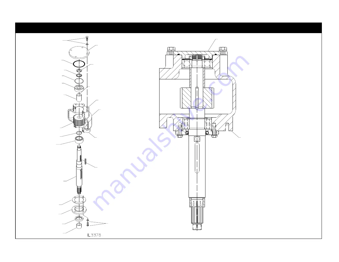
Disassembly - Disassemble Cap (Continued)

Bearing Cover

Single Row Bearing

Front Cap Flange

Spacer

Double Row
Bearing

Driven Shaft

Shim, .010 in.

Oil Seal Housing

Oil Seal

Yoke Spacer

Four (4) 3/8-16 x 1 in.
Screws and Lockwashers

Rear Cap Flange

Four (4) 3/8-16 x 1 in.
Screws and Lockwashers

Rear

Driven Sprocket

Key

Bearing Locknut

Wave Spring

Bearing Lock nut

Front

Eclipse ES™ CAFS on Rear of PTO

1.

Remove the screws from the bearing cover  and
oil seal housing. Remove cover and housing. Dis­
card the oil seal.

2.

Straighten tab of the bearing lockwasher from slot
in bearing lock nut and then remove the locknut,
lockwasher and wave spring.

3.

Under a press, support the assembly on the rear
face side of the cap and apply a press load to the
end of the driven shaft to press the shaft out of the
ball bearing, spacer and sprocket. Rear bearing
and retaining ring will come out with the driven
shaft. Remove from shaft.

4.

Remove the ball bearing, spacer and sprocket
from cap.

Cap

Bearing Lockwasher

O-ring

Retaining Ring

Summary of Contents for TC20 Series

Page 1: ...ge without notice Waterous Company 125 Hardman Avenue South South St Paul Minnesota 55075 USA 651 450 5000 www waterousco com T 365 Revised 9 24 20 Table of Contents TC20 Chain Driven Power Take Off O...

Page 2: ...Shift Fork 19 Removal of Coupling Output Shaft 21 Removal of Drive Input Shaft Shift Collar Retaining Ring Input Shaft Only Configurations 22 Pressing Out Drive Shaft 23 Removing Drive Shaft Sprocket...

Page 3: ...Output Shaft Configurations 52 Input Shaft Only Configurations 52 Chain 53 Coupling Output Shaft Input and Output Shaft Configurations Wave Spring Design Prior to March 12 2013 54 Shim Design After Ma...

Page 4: ...n ent from Service Parts List along with the PTO Model serial number Gasket and O ring repair kit Part No K 1117 is available from Waterous that includes all the gaskets and O rings required for a com...

Page 5: ...ness of its internal parts Sand dirt or other abrasive material will wear gears and related parts Before disassembling a PTO for repairs be sure to clean its exterior Make sure the working space bench...

Page 6: ...2 in Mild Steel Plate Material 4 in Schedule 40 PVC Pipe Reference Page 18 Bracket is not available from Waterous and must be fabricated NOTE Provisions must be made to secure bracket to jack Fastene...

Page 7: ...Material 2 1 2 NPT x 4 00 in Long Pipe Nipple Drive Input Shaft Installation Sleeve Assembly Waterous Part No 63432 Reference pages 48 52 and 54 56 This sleeve is used when installing the Driveline in...

Page 8: ...art No 63596 Reference page 58 This tool is to be used to ensure a 1 1 8 in 29mm area around the lubrica tion return holes in the case and cap are free of silicone This tool is available from Waterous...

Page 9: ...Driveline Output Not required if PTO is configured with an input shaft only Disconnect propeller shaft driveline at the PTO input and output shafts and the PTO output shaft NOTE Driveline is furnishe...

Page 10: ...ut Disconnect Output Shaft Disconnect hydraulic pump from PTO Remove two 2 1 2 13 screws and lockwashers Slide hy draulic pump away from PTO to dis engage splines on shafts NOTE Hydraulic Pump is furn...

Page 11: ...ming Pump Remove Priming Pump from Transmission Power Cable to Battery Ground Cable to Chassis Wiring to Priming Valve Hose to Priming Valve Optional Lubricant Line Input Side of PTO Four 4 3 8 16 x 1...

Page 12: ...T 365 Page 12 of 75 Disassembly Disconnect Optional Accessories Shift Unit Oil Temperature Sensor...

Page 13: ...NOTE The Oil Cooler and Compressor Sump are mounted remotely from the PTO in the vehicle Oil Cooler T 365 Page 13 of 75 Disassembly Disconnect Optional Accessories Eclipse ES CAFS on Rear Output WARN...

Page 14: ...assembly 4 Disconnect cable to Auto Sync panel Air line from Air Oil Separator 4 JIC Connection Oil Scavenger line from Air Oil Separator 4 JIC Connection Cable to Auto Sync Panel 4 Air line from vehi...

Page 15: ...ound wire from electrical relay panel NOTE Label wires to ease reassembly 6 Disconnect wires from Oil Temperature Switch located on the compressor oil sump Compressor Oil Sump Mounted remotely from pu...

Page 16: ...e drain plug from case 2 Place a PTO jack with PTO case support bracket attached see Page 6 for construction details under the PTO 3 Free PTO from all mounting brackets securing it to the chassis Brac...

Page 17: ...nd yoke and nut b Remove end yoke sleeve c Remove the 3 8 16 set screw on the clutch hub Access set screw through slot in sprocket d Slide the air clutch off of the shaft e Remove the clutch key from...

Page 18: ...s Part No K1117 1 Remove twelve 12 3 8 16 x 1 in screws from oil pan 2 Remove oil pan and gasket 3 If a new O ring is required note that a new O ring is included in gasket kit Waterous Part No K1117 D...

Page 19: ...16 x 1 in mounting screws and washers 3 Pull shift unit straight back as far as possible 4 Rotate shift unit towards case to disengage clevis from shift fork 3 8 in Hex Socket Shift collar to PUMP PT...

Page 20: ...ssembly Removal of Driveline from Case Continued Shift Fork Step 2 Shift Fork Step 3 Rotate fork and pull down to remove fork from case Step 3 Push slotted end of shift fork towards sprocket to clear...

Page 21: ...of case 1 Remove six 6 3 8 16 x 1 in screws and lockwashers 2 Install 3 8 16 x 1 in screws in jacking screw holes and tighten to disengage coupling shaft housing from case Input and Output Shaft Conf...

Page 22: ...moval of Driveline from Case Continued Removal of Drive Input Shaft Shift Collar Retaining Ring Input Shaft Only Configurations Remove retaining ring loc ated behind shift collar Leave shift collar in...

Page 23: ...ing to level the case Drive Input Shaft Shift Collar Use suitable blocking to level case if cap is left attached to case Drive Shaft Removal Sleeve Waterous Part No 63431 see Page 6 CAUTION If shaft h...

Page 24: ...ill be loose Sprocket Shift Collar Step 3 Remove case from the press and remove components as shown Bearing will remain on shaft Remove drive input shaft Note that the sprocket must be supported while...

Page 25: ...e Input Shaft Transmission Case Support Bracket Housing Sprocket Shift Fork Shoes Shaft Remove bearing from shaft 2 2 1 3 1 Remove O ring 2 Remove oil seal 3 Remove bearing 1 1 Remove both needle bear...

Page 26: ...ve O ring from housing 5 Remove outer bearing and spacer from shaft Access Holes a Pull outer ball bearing from the shaft b Remove the spacer and pull inner ball bearing from the shaft Note that due t...

Page 27: ...varies slightly use the diagram below to determine the output connection on your PTO Type Connection on Front Input Shaft Side Connection on Rear Output Shaft Side See Page Disassembly Reassembly Sing...

Page 28: ...28 of 75 Disassembly Removal of Output Shaft Remove Cap from Case TC20B Models TC20C Models TC20D TC20E and TC20F Models Note The two 2 slots in the case flange may be used to help separate the cap fr...

Page 29: ...cknut 2 Remove the screws that fasten the bearing cover and oil seal hous ing to the cap Remove cover and housing Discard the oil seal 3 Straighten tab of the bearing lockwasher from slot in bearing l...

Page 30: ...ews that fasten the bearing cover and oil seal hous ing to the cap Remove cover and housing Discard the oil seal 3 Straighten tab of the bearing lockwasher from slot in bearing lock nut and then remov...

Page 31: ...draulic pump adapter and bearing cover to the cap Remove adapter and cover Discard the oil seal 2 Straighten tab of the bearing lockwasher from slot in bearing lock nut and then remove the locknut loc...

Page 32: ...nd bearing cover to the cap Remove adapter and cover Discard the oil seal 2 Straighten tab of the bearing lockwasher from slot in bearing lock nut and then remove the locknut lockwasher and wave sprin...

Page 33: ...Remove the screws from the bearing cover and oil seal housing Remove cover and housing Dis card the oil seal 2 Straighten tab of the bearing lockwasher from slot in bearing lock nut and then remove th...

Page 34: ...ke and locknut Discard locknut 2 Remove the screws that fasten the hydraulic adapter and oil seal housing to the cap Remove adapter and housing Discard oil seals 3 Remove retaining ring from shaft 4 U...

Page 35: ...and locknut Discard locknut 2 Remove the screws that fasten the hydraulic adapter and oil seal housing to the cap Remove adapter and housing Discard oil seals 3 Remove retaining ring from shaft 4 Unde...

Page 36: ...ling Ball Bearings Keep new ball bearings wrapped until they are to be installed When pressing the ball bearing on a shaft or into a bore coat appropriate sur faces with grease Shaft grease shaft and...

Page 37: ...ket inside the cap 8 Take the driven shaft bearing and key assembled previously and from the front face of the cap slide the shaft through the bore in the cap into the bore of the driven sprocket spac...

Page 38: ...ide the cap 8 Take the driven shaft bearing and key assembled previously and from the rear face of the cap slide the shaft through the bore in the cap into the bore of the driven sprocket spacer and b...

Page 39: ...n sprocket inside the cap 8 Take the driven shaft bearing and key assembled previously and from the front side of the cap slide the shaft through the bore in the cap into the bore of the driven sprock...

Page 40: ...iven sprocket inside the cap 8 Take the driven shaft bearing and key assembled previously and from the rear face of the cap slide the shaft through the bore in the cap into the bore of the driven spro...

Page 41: ...reviously and from the rear face of the cap slide the shaft through the bore in the cap into the bore of the driven sprocket spacer and ball bearing lining up the key in the shaft with the keyway in t...

Page 42: ...resting on the rear face position the spacer and driven sprocket inside the cap 8 Take the driven shaft bearing and key assembled previously and from the front side of the cap slide the shaft through...

Page 43: ...h the cap resting on the front face position the spacer and driven sprocket inside the cap 8 Take the driven shaft bearing and key assembled previously and from the rear face of the cap slide the shaf...

Page 44: ...T 365 Page 44 of 75 Reassembly Attach Cap to Case Apply Sealant...

Page 45: ...ssembly Case Cap Install two 2 dowel pins if they were removed dur ing disassembly Shim Install shims if ne cessary refer to service parts list for quantity and thickness of shims for each PTO model v...

Page 46: ...et 2 Install needle bearing larger radius edge first just below bot tom of chamfer on sprocket bore Install bearing on shaft Bearing O ring 4 3 4 x 5 in Housing Oil Seal 3 1 2 x 4 3 8 in 1 Install bea...

Page 47: ...nput and Output Shaft Configuations Step 2 Input and Output Shaft Configurations Step 3 Sub Assembly Shaft Oil Seal 3 1 2 x 4 3 8 in Coupling Shaft Housing Housing with groove ring on the flange requi...

Page 48: ...e Install Tachometer Ring in Installation Tool 1 Grease O ring 2 Install drive shaft housing assembly on case with six 6 3 8 16 x 1 in screws and lockwashers Torque to 31 lb ft Install tachometer ring...

Page 49: ...installation sleeve on an arbor press 5 Place case on drive shaft installation sleeve Use ap propriate blocking to level the case NOTE Alignment is done with drive shaft housing and installation sleev...

Page 50: ...assembly Installation of Driveline in Case Continued Drive Input Shaft Install Drive Sprocket 6 Install thrust washer in case cen tering bore with bearing 7 Install drive sprocket in case cen tering b...

Page 51: ...365 Page 51 of 75 Reassembly Installation of Driveline in Case Continued Drive Input Shaft Install Drive Shaft in Case 8 Press drive shaft assembly into case and through sprocket and drive shaft housi...

Page 52: ...onfiguration 9b Install retaining ring in groove on drive shaft spline behind shift collar 9a Install shift collar on drive shaft slide over spline teeth on both drive shaft and sprocket Install shift...

Page 53: ...g side the con necting rocker The two wide curved surfaces of the con necting pin and connecting rocker must face each other 4 After the connecting pin assembly and connecting rocker have been pushed...

Page 54: ...Design Prior to March 12 2013 Coupling Shaft Housing Assembly Grease O ring Drive Shaft Bearing Six 6 3 8 16 x 1 in Screws and Lockwashers Torque to 31 lb ft 10 Grease O ring on coupling shaft housing...

Page 55: ...p the end of the coupling shaft with a soft mallet to force the driveline all the way forward Do not overtighten causing bending or breakage of the coupling shaft housing 2 Measure the gaps between th...

Page 56: ...y Shaft Configuration Grease O ring Bearing Housing Six 6 3 8 16 x 1 in Screws and Lockwashers Torque to 31 lb ft Drive Shaft Bearing 10 Grease O ring on bearing housing 11 Press bearing housing on dr...

Page 57: ...In both drive and coupling shaft housings 13b Input Shaft Only Configuration In drive shaft housing only 14 If PTO is equipped with an option al tachometer install sensor in drive shaft housing as fo...

Page 58: ...e Continued Shift Fork Step 1 Step 2 Place collar in PTO position Slide shift fork onto shift collar in case Ensure shift shoes are installed see Page 46 Step 1 Sprocket Pull arm of shift fork away fr...

Page 59: ...g fork arm towards end of case where the shift unit mounts 4 Rotate shift unit towards case and engage clevis in shift fork slot 5 Push shift unit straight back in until flange contacts case 6 Install...

Page 60: ...12 3 8 16 x 1 in screws and lockwashers Torque to 31 lb ft Note Before tightening fasteners push the oil pan towards front of PTO to properly position oil pan against inner wall of the PTO case 1 Lub...

Page 61: ...T 365 Page 61 of 75 Reassembly Installation of Driveline in Case Continued Cross Section Diagram of Driveline Input and Output Shaft Configurations...

Page 62: ...T 365 Page 62 of 75 Reassembly Installation of Driveline in Case Continued Cross Section Diagram of Driveline Input Shaft Only Configuration WITHOUT TACHOMETER WITH OPTIONAL TACHOMETER INPUT END...

Page 63: ...air clutch as follows a Apply Loctite 609 to keyway in the shaft and install the key on the shaft b Apply anti seize to the shaft and slide the air clutch onto the shaft until the set screw holes alig...

Page 64: ...pound load to the belt midway between the drive and driven sprocket The belt should deflect between 250 and 313 inches c Once the proper belt tension is achieved tighten the idler sprocket by turning...

Page 65: ...of PTO in Vehicle 5 1 4 1 Secure PTO to support bracket on PTO jack 2 Raise PTO up into vehicle 3 Connect PTO to original mounting brackets in vehicle NOTE Ensure pump and PTO are within 1 8 before i...

Page 66: ...66 of 75 Reassembly Installation of PTO in Vehicle Continued Connection of Propeller Shaft Driveline Connect vehicle propeller shafts to PTO NOTE Output shaft is not used for in put shaft only PTO con...

Page 67: ...on Rear or Front Output End Yoke on Front or Rear Output Install hydraulic pump on PTO using two 2 1 2 13 screws and lockwashers Torque to 75 lb ft NOTE Hydraulic Pump is furnished and installed by t...

Page 68: ...optional tachometer thread cable onto sensor in housing Priming Pump Hose Connections Connect hose from priming valve If lubricant is used for the priming pump connect tubing to lubricant tank Install...

Page 69: ...T 365 Page 69 of 75 Reassembly Installation of PTO in Vehicle Continued Connection of Optional Accessories Priming Pump Wiring Connections...

Page 70: ...T 365 Page 70 of 75 Reassembly Installation of PTO in Vehicle Continued Connection of Optional Accessories Shift Unit Oil Temperature Sensor...

Page 71: ...bricant See Page 72 Air line from Air Oil Separator 4 JIC Connection Oil Scavenger line from Air Oil Separator 4 JIC Connection Cable to Auto Sync Panel 2 Air line from vehicle air supply 1 4 NPT Conn...

Page 72: ...al Accessories Compressor Oil Sump Mounted remotely from pump on the vehicle Oil Temperature Switch Ground Power Note that three 3 wires are connected to Terminal No 4 Green Wire Large Terminal Yellow...

Page 73: ...T 365 Page 73 of 75 Reassembly Installation of PTO in Vehicle Continued Connection of Optional Accessories Wiring Schematic Eclipset ES CAFS on Rear Output Electric Wiring Continued...

Page 74: ...eners for tightness 3 Check for fluid leaks 1 Fill the compressor sump with oil Use ISO 68 viscosity oil System holds approximately 2 to 3 gallons The oil level should be approxim ately half way up th...

Page 75: ...ervice foot brake and release the parking brake a Ensure that the green OK TO PUMP light in the cab is off b Ensure that the green THROTTLE READY light on the operator s panel is off 4 Engage the park...

Reviews: