


Safety Guide
Check and comply with your provincial /
state and local codes. You must follow
these guidelines.
Use care when handling the water soften-
ing system. Do not turn upside down,
drop, drag or set on sharp protrusions.
The water softening system works on 12
volt-60 Hz electrical power only. Be sure to
use only the included transformer.
Transformer must be plugged into an in-
door 120 volt, grounded outlet only.
Use clean water softening salts only, at
least 99.5% pure. NUGGET or PELLET
salts are recommended. Do not use rock,
block, granulated or ice cream making
salts. They contain dirt and sediments, or
mush and cake, and will create mainte-
nance problems.
Keep the salt lid in place on the softener
unless servicing the unit or refilling with
salt.
WARNING
: This system is not in-
tended for treating water that is microbio-
logically unsafe or of unknown quality
without adequate disinfection before or
after the system.
For your safety, the information in this manual must be followed to minimize the risk of
electric shock, property damage or personal injury.
Be sure to check the entire softener for any shipping damage or parts loss. Also note dam-
age to the shipping cartons. Contact the transportation company for all damage and loss
claims. The manufacturer is not responsible for damages in transit.
Small parts, needed to install the softener, are in a parts bag. To avoid loss of the small
parts, keep them in the parts bag until you are ready to use them.
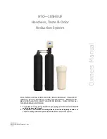
Unpacking / Inspection
PAGE
Unpacking / Inspection
2
Safety Guide
2
Proper Installation
3
Specification 4
Before Starting Installation
4
Installation Instructions
6
System Start Up
8
Programming Instructions
9
About The System
10
Maintenance 12
Sanitizing Procedure
15
Main Repair Parts
17
Trouble Shooting
22
Warranty 23
Table of Contents
2
Summary of Contents for HTO-185HEUF
Page 7: ...Installation 7...
Page 20: ...Power Head Exploded View 20...