


14
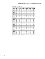
PREMIER 2 SINGLE-SPEED INSTALLATION AND MAINTENANCE MANUAL
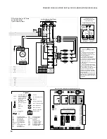
ECM2
Fan Motor
NOTE 9
P11
2
3
4
5
1
PB2
4
3
2
1
Auxiliary Electric Heat Power
208-230/60/1
G
Violet
Blu
With optional Premier ' EA' Series
Auxiliary ElectricHeat
Typical schematic shown
2
3
HE1
TS1
HE2
HE3
TS3
HE4
TS4
1
2
3
4
P7
L4
L2
L2
G
NOTE 5
Grn
Pink
Yel
Blk
Gray
Pink
Yel
Blk
Gray
Gray
Blk
Yel
Pink
Gray
Pink
Blk
Yel
Pink
Yel
Blk
Gray
Pink
Yel
Blk
Gray
Grn
P8
F2
P9
ER1
ER2
ER3
ER4
L1
L1
L3
NO
NO
NO
NO
Brn
Or
Brn
Or
5
4
Pink
Orange
White
Tan
Blue
15
10
16
3
8
On/Off
PWM
RPM
C2
RPM grnd
P12
Violet
Blue
Yellow
Black
Gray
Red
Premier2
EA Series PCB
17P514A01
T
1
3
2
G
P
Thermistor
Light emitting diode - Green
Relay coil
Capacitor w/ bleed resistor
Switch - Condensate overflow
Switch - High pressure
Switch - Low pressure
Switch -Hot water On/Off
Polarized connector
Factory low voltage wiring
Factory line voltage wiring
Field low voltage wiring
Field line voltage wiring
Optional block
DC voltage PCB traces
Internal junction
Quick connect terminal
Wire nut
Field wire lug
Ground
Fuse
L1
CC -
CO -
CR1 -
CR2-
CR3 -
CR4 -
ER1 to ER4 -
F1 and F2 -
FP -
HE -
HP -
HWL -
LP -
PB1, PB2 -
PS -
RV -
SW1 -
SW2 -
SW3 -
SW4 -
TS -
Compressor contactor
Condensate overflow sensor
DHW pump relay
Loop pump relay
PSC fan speed relay
PSC fan power relay
Aux heat stage relays
Fuses
Freeze protection sensor
Heater element
High pressure switch
Hot water limit sensor
Low pressure switch
Power blocks
Power strip
Reversing valve coil
DIP package 12 position
DIP package 8 position
DIP package 5 position
Hot water pump enable switch
Thermal limit switch
Legend
Relay contacts-
N.O., N.C.
Notes:
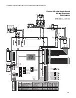
L1
L2
Single Disconnect Power
208-230/60/1
Aux Elect Power
208-230/60/1
L1
L2
L1
L2
AT Unit Power
208-230/60/1
CSA installed units only
Local codes may require a single
source of power supply
Breaker box
furnished by
installer
Circuit Breakers
1 2 3
1
P4
On
Off
SW1
240V - L2
240V - L1
Fused L2
Fused L2
Fused L2
F1
F1
R
R
Microprocessor
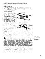
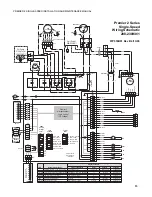
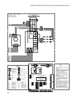
Premier2 Series Logic Board
Premier2 Logic Board (Single-Speed Configuration) Physical Layout
CR2- Loop Pump
N.O.
240V - L2
240V - L1
C
C
1
2
3
4
5
6
7
8
9
10
11
12
13
14
15
16
P6
1
2
3
4
5
6
7
8
9
10
11
12
13
14
P5
Fused L2
Fused L1
CR1- DHW Pump
N.O.
N.O.
CR4
Com
CC
CC-GND
CCLO
CCHI
1
2
ACC
NO
ACC
NC
3
ACC
COM
P3
2
3
4
5
6
7
8
9
10
11
12
1
On
Off
SW2
2
3
4
5
6
7
8
1
On
Off
SW3
2
3
4
5
N.O.
CR3
Com
N.C.
P1
R
C Y1 Y2
G
O
W
LO
1
2
3
4
5
6
7
8
C
C
SL1
IN
2
3
4
5
SL1
Out
P2
SL2
IN
6
7
SL2
Out
1
Shut
Down
1
1
2
3
P10
4
5
6
P2
1
TS2
1 - Switch blue and red wires for 208V
operation.
2 - Connection of remote unit that does not
have a loop pump for slave operation.
3 - 24V Accessory relay (see SW2 - 3 for
description of operation).
4 - The blk/wh and gray/wh wires are
removed when Aux Heat is installed .
5 - Buss lugs L1 and L2 can be removed and
dual power wire sets connected directly to
box lugs L1, L2, and L3, L4.
6 - DHW pump only in models with hot water
generation option.
7 - Air Flow Configuration Example: SW1
configured for dip 3 as low, dip 5 as medium,
and dip 7 as high speed ECM2 fan.
8 - SW3-4 should be in the ON position when
using Premier 2 Electric Heat control
17P514A01, and it should be in the OFF
position when using Premier Electric Heat
control 17P501A01.
9 - When using thermostat TA32E12, SW2 -8
should be in the "on" position. When using
24VAC thermostats, SW2-8 should be in the
"off" position.
Summary of Contents for AT019D
Page 20: ......
Page 21: ......
Page 26: ...26 PREMIER 2 SINGLE SPEED INSTALLATION AND MAINTENANCE MANUAL Notes...
Page 27: ...27 PREMIER 2 SINGLE SPEED INSTALLATION AND MAINTENANCE MANUAL...


