2
PREMIER 2 SINGLE-SPEED INSTALLATION AND MAINTENANCE MANUAL
Physical Data
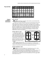
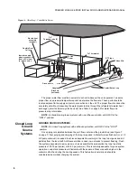
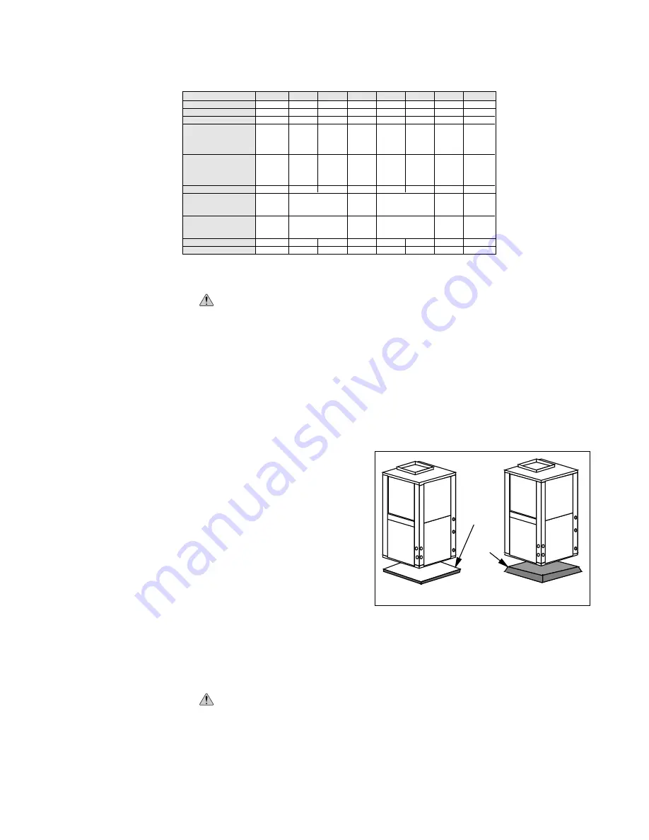
Figure 1
–
Vertical Unit Mounting
UNIT LOCATION
CAUTION:
Do not locate in areas where ambient conditions are not maintained within
45
°
-95
°
F and less than 75% relative humidity.
Locate the unit in an indoor area that allows for easy removal of the filter and access panels.
Location should have enough space for service personnel to perform maintenance or repair.
Provide sufficient room to make water, electrical and duct connection(s). If the unit is located in a
confined space, such as a closet, provisions must be made for return air to freely enter the space
by means of a louvered door, etc. Any access panel screws that would be difficult to remove
after the unit is installed should be removed prior to setting the unit. On horizontal units, allow
adequate room below the unit for a condensate drain trap and do not locate the unit above
supply piping. These units are not approved for outdoor installation and, therefore, must be
installed inside the structure being conditioned.
SETTING VERTICAL UNITS
Vertical units are available in left or
right air return configurations. Top flow
vertical units should be mounted level on a
vibration absorbing pad slightly larger than
the base to provide isolation between the
unit and the floor. It is not necessary to
anchor the unit to the floor (see Figure 1).
Bottom flow units should be mounted level
and well sealed to the floor to prevent
air leakage.
NOTE:
If access to the left side of the
unit will be limited after installation, remove the two mounting screws on the left side of the
control box before setting the unit (leave the two front mounting screws intact). This will allow the
control box to be removed with only the two front mounting screws for future service.
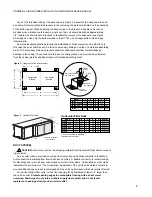
SETTING HORIZONTAL UNITS
CAUTION:
Do not use rods smaller than 3/8” diameter since they may not be strong
enough to support the unit. The rods must be securely anchored to the ceiling.
Horizontal units are available with side or end discharge and may be field converted from one
to the other by replacing the discharge panel (TB920813) with a new panel which must be
ordered separately. Horizontal units are normally suspended from a ceiling by four 3/8” diameter
threaded rods (six on ATH040-066). The rods are usually attached to the unit by hanger bracket
kits furnished with each unit.
General
Installation
Information
AAAAA
AAAAA
AAA
AAA
AAA
AA
AA
AA
AA
Vibration
Absorbing
Mesh
Air
Pad
AT022C/D
AT019D
MODEL
AT028D AT034D AT040D AT046D AT056D AT066D
9 x 7
ECM2-1/2
Rotary
19 x 20
2.6
3
18 x 21
2.6
3
43.0
189
210
20 x 24
EAF2024
18 x 24
EAF1824
24 x 24
EAF2424
2-18 x 18
EAF1836
9 x 7
ECM2-1/2
Scroll
24 x 20
3.3
3
18 x 27
3.4
3
62.0
258
260
9 x 7
ECM2-1/2
Rotary
24 x 20
3.3
3
18 x 27
3.4
3
58.0
252
256
11 x 10
ECM2-1/2*
Scroll
28 x 25
4.9
3
20 x 35
4.9
3
85.0
320
337
11 x 10
ECM2-1/2*
Scroll
28 x 25
4.9
3
20 x 35
4.9
3
88.0
336
339
9 x 7
ECM2-1/2*
Scroll
27 x 20
3.8
3
18 x 30
3.8
3
65.0
274
270
2-14 x 24
EAF2428
2-18 x 18
EAF1836
Fan Wheel
Fan Motor
Compressor
Air Coil: (Vertical)
Dimensions
Area (sq. ft.)
Rows
Air Coil: (Horizontal)
Dimensions
Area (sq. ft.)
Rows
R22 (oz.)
Filter-1" (Vertical)
Throwaway
Electrostatic
Filter-1" (Horizontal)
Throwaway
Electrostatic
Weight (lbs.)-Vertical
Weight (lbs.)-Horizontal
* Optional 1 hp ECM2 fan motor available
11 x 10
ECM2-1
Scroll
32 x 25
5.6
3
20 x 40
5.6
3
116.0
2-10x30
1-12x30
EAF2042
1-18x20
1-24x20
EAF2042
399
429
11 x 10
ECM2-1
Scroll
36 x 25
6.3
3
20 x 45
6.3
3
98.0
3-12x30
EAF2048
2-24x20
EAF2048
426
456
2-14 x 30
EAF2830
1-20 x 12, 1-20 x 25
EAF2037
Summary of Contents for AT019D
Page 20: ......
Page 21: ......
Page 26: ...26 PREMIER 2 SINGLE SPEED INSTALLATION AND MAINTENANCE MANUAL Notes...
Page 27: ...27 PREMIER 2 SINGLE SPEED INSTALLATION AND MAINTENANCE MANUAL...


