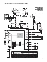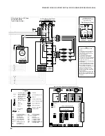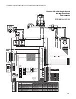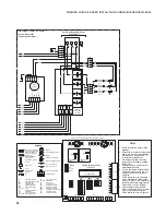
19
PREMIER 2 SINGLE-SPEED INSTALLATION AND MAINTENANCE MANUAL
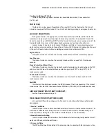
4-Dehumidification/Normal. Fan speed control
This DIP switch allows field selection of the dehumidification mode, which uses the low
and medium fan speeds for cooling or the medium and high fan speeds for cooling in the
normal mode.
5-Auxiliary Off
This DIP switch disables third-stage heating. Full emergency heat would in any event still be
available if needed.
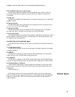
6-Diagnostics-Inputs
This DIP switch allows viewing the inputs from the thermostat to the control board such as
Y1, Y2, O, G, W, SL1-In on the LED display.
7-Diagnostics-Outputs
This DIP switch allows viewing the outputs from the control board such as compressor,
reversing valve, blower, hot water pump, and loop pump on the LED display.
8-Thermostat Selection
This DIP switch allows field selection of thermostat type connected to the Premier 2 control. If
using a TA32E12, the DIP switch must be in the ON position. The DIP switch should be in the
OFF position for 24 VAC thermostats.
FACTORY SETUP DIP SWITCHES (SW3)
A 5-position DIP switch package on the Premier 2 control allows the following factory setup
options:
1-Two-Speed/Single-Speed
This DIP switch configures the control for single-speed compressor operation or two-speed
compressor operation.
2-ECM/ECM2
This DIP switch configures the control to operate with the ECM blower motor (motor with
square control on end) or with the ECM2 (round) blower motor.
3-No RPM/RPM
This DIP switch configures the control to monitor the RPM output of an ECM/ECM2 blower
motor. When using a PSC blower motor, the control should be configured for no RPM sensing.
4-AT EH Board/Premier 2 EH Board
This DIP switch configures the control to operate with the Premier 2 electric heat control
board (6-position connector) or with the AT electric heat control board (3-position connector).
5-Future Use
Not used at this time.
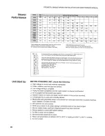
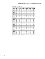
ECM2 blower motors have a 12-speed selector DIP switch on the Premier 2 logic board
(SW1) and are factory set for optimum performance. To change speeds, select the appropriate
speeds on DIP switch SW1. Refer to the blower performance table for specific airflow and
switch information.
Blower Speed
Summary of Contents for AT019D
Page 20: ......
Page 21: ......
Page 26: ...26 PREMIER 2 SINGLE SPEED INSTALLATION AND MAINTENANCE MANUAL Notes...
Page 27: ...27 PREMIER 2 SINGLE SPEED INSTALLATION AND MAINTENANCE MANUAL...

