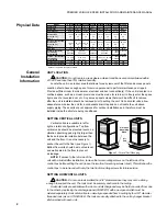
3
PREMIER 2 SINGLE-SPEED INSTALLATION AND MAINTENANCE MANUAL
DUCT SYSTEM
CAUTION:
Be sure to remove the shipping material from the blower throat before connect-
ing ductwork.
An air outlet collar is provided on vertical top flow units and all horizontal units to facilitate a
duct connection (vertical bottom flow units have no collar). A flexible connector is recommended
for discharge and return air duct connections on metal duct systems. Uninsulated duct should be
insulated with a minimum of 1" duct insulation. Application of the unit to uninsulated ductwork in
an unconditioned space is not recommended as the unit’s performance will be adversely affected.
For vertical bottom flow units, cut the floor opening for air discharge at least 1/2" larger than
the unit air outlet. Protect opening edges in combustible flooring with a sheet metal
overwrap. Discharge air only into a suitable supply duct system and do not locate
registers or openings directly under unit air outlet.
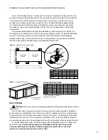
Lay out the threaded rods per the dimensions in Figure 2. Assemble the hangers to the unit
as shown. Securely tighten the brackets to the unit using the weld nuts located on the underside
of the bottom panel. When attaching the hanger rods to the bracket, a double nut is recom-
mended since vibration could loosen a single nut. The unit should be pitched approximately
1/4” towards the drain in both directions to facilitate the removal of condensate. (see Figure
5A on page 5). Use only the bolts provided in the kit. The use of longer bolts could damage
internal parts.
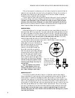
Some residential applications require the installation of horizontal units on an attic floor. In
this case, the unit should be set in a full size secondary drain pan on top of a vibration absorbing
mesh. The secondary drain pan prevents possible condensate overflow or water leakage
damage to the ceiling. The secondary drain pan is usually placed on a plywood base isolated
from the ceiling joists by additional layers of vibration absorbing mesh.
A
C
B
D
E
Air Handler
Section
Compressor
Section
Figure 2–
Hanger Location and Assembly
Bolt and
Lockwasher
Vibrator
Isolator
Washer
3/8" Threaded Rod
(not supplied)
Hex Nuts
(not supplied)
MODEL
C
B
A
D
E
ATH019
ATH022, 028, 34
ATH040, 046
ATH056
ATH066
24.8
24.8
27.8
27.8
27.8
-
-
29.9
29.9
29.9
51.5
61.5
70.5
75.5
80.5
53.0
63.0
72.0
77.0
82.0
22.5
22.5
25.5
25.5
25.5
Figure 3–
Optional Filter Rack
D
C
A
B
E
Door side mountable
on either end
Horizontal Filter Rack
MODEL
C
B
A
D
E
Model No.
24.5
36.1
36.1
37.1
42.1
47.1
5.5
5.5
5.5
5.5
5.5
5.5
DCH1824
DCH1836
DCH1836
DCH2037
DCH2042
DCH2048
18.1
18.1
18.1
20.1
20.1
20.1
0.5
0.5
0.5
0.6
0.6
0.6
2.5
2.0
2.0
2.2
2.2
2.2
1" duct connection is provided.
Construction is air tight.
ATH019
ATH022, 028
ATH034
ATH040, 046
ATH056
ATH066
Summary of Contents for AT019D
Page 20: ......
Page 21: ......
Page 26: ...26 PREMIER 2 SINGLE SPEED INSTALLATION AND MAINTENANCE MANUAL Notes...
Page 27: ...27 PREMIER 2 SINGLE SPEED INSTALLATION AND MAINTENANCE MANUAL...


