2. INSTALLATION PERSONNEL SECTION
2.1. BOILER INSTALLATION RULES
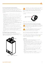
2.1.1. General Rules for Installatıon Place of the Boiler
There are not any ventilation limitations for areas where hermetic
(C type) boiler is to be installed (it can be installed independent of
the volume and ventilation of the room). It can also be installed in
protected areas like balcony and terrace provided that it is placed in a
protective closure and that precautions against freezing of the system
water are taken. The boiler shall be securely mounted to the building
wall. A flexible joint shall be used between the boiler and gas line.
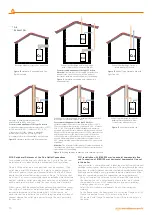
Lengths of the flex ducts to be used in Type A, B and C appliances
shall not exceed the values permitted by the local gas authority. Flue
outlets of hermetic boilers must be connected to the areas which
are directly open to outside area, and have sufficient air circulation.
Conditions of exhaust gas system gas outlets of these appliances
(position of the pipe outlets in various forms, vertical, horizontal
minimum distances, cross-sectional areas of ducts if used, etc.) shall be
in compliance with TS 12514 standard.
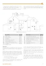
2.1.2. Places where hermetic boilers cannot be installed
• Stairwells of buildings,
• common aisles, ventilation ducts, garret, attics, emergency exit doors,
storage rooms and other similar common areas,
• Yards between buildings,
• Narrow gaps between eaves
• On the chimney walls,
• Closed balconies,
• Open balconies (except placed in an enclosure and permitted by
the manufacturer),
• Under the extending structures hindering outlet of exhaust gas,
• Places exposed to direct wind force,
• Openings supplying fresh air to other units (C type) It is forbidden to
install hermetic boilers at places specified above!
2.1.3. Mounting of the Boiler to Wall and Selection of Installation
Place
• Mounting of the boiler to wall must be checked and ensured to be
stable and safe.
• The hanger plate and connection screws supplied with the boiler
shall be mounted on a filled or semi-filled brick wall in accordance
with the installation scheme, and shall not be used for other
purposes.
• In case any different materials are used for mounting, the warranty
of the boiler shall be terminated.
• If the wall to which the boiler is to be mounter is not brick, strength
of the support system shall be checked.
• The boiler shall be mounted on a fire resistant wall.
• The boiler should be mounted so as the height of the hanger plate
to be between 1,8-2,2 mm from the ground.
• The boiler shall be mounted with gaps as minimum 30 cm above
the ground, minimum 5 cm from both sides and minimum 90 cm
from the front side where the installation area is limited, for allowing
easy intervention of the service technician.
• The boiler shall not be installed in areas which contain or may
contain explosives, flammables and acid vapors.
• It shall not be installed next to or above ovens, cookers, radiators or
heaters.
• Hermetic boilers can also be installed in cabinets, provided that
minimum 5 cm from each side is left.
• If the boiler is to be mounted over the kitchen countertop or
kitchen set, there shall be a minimum 50 cm distance under the
boiler.
• Due to possibility of water draining from the Safety Valve of the
boiler after mounting, the outlet shall be connected to the drainage
line. If this is not possible; do not place electronic appliances, and
tools, parts and materials which may breakdown, be deformed or
form rust.
• Any furniture should not be placed under the boiler due to the
reasons specified above.
• Make sure that there are no liquids or inflammable materials in the
immediate vicinity of the boiler.
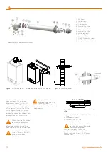
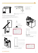
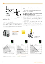
Figure 6
Viwa 50 / Viwa 65 boiler dimensions and connections
Warmhaus Viwa 50 / 65
1) 230 V AC Main Power Supply
2) Manometer
3) Safety Valve Drainage Line
4) Gas Inlet Line
5) Heating Supply Line
6) Heating Return Line
7) Condensate Drainage Line
8) Sediment-Air Separator Discharge
9) Heating/Domestic Hot Water MODE
Button
10) Heating Temperature Increasing
Setting Button,
11) Heating Temperature Reducing
Setting Button
12) LCD Display
13) Service Port
14) RESET Button
15) Domestic Hot Water Temperature
Increasing Setting Button
16) Domestic Hot Water Temperature
Reducing Setting Button
17) Exhaust gas/Flue outlet
18) Hanger plate
70
0
4
158
7
65
207
124
127
207
127
725
30
385
420
40
100
121,5
105,5
90
88,5
136
MODE
RESET
+
-
-
+
1
2
3
4
5
6
7
9
10
11
12
13
14
15
16
17
18
Kalorifer Gidiş
G1 1/4
Kalorifer Dönüş
G1 1/4
GAZ
G 3/4
1
2
9
8
7
6
5
4
3
10
11
12
13
14
15
16
17
230V AC MAIN SUPLLY
MANOMETER
PRESSURE RELIEF VALVE OUTLET
GAS INLET
CENTRAL HEATING FLOW (CH)
CENTRAL HEATING RETURN (CH)
CONDANSATE DRAIN
CH/DHW MODE PUSH BUTTON
DIRT COLLECCTOR DRAIN
CH TEMPERATURE - ADJ. BUTTON
LCD DISPLAY
SERVICE ACCESS POINT
RESET BUTTON
DHW TEMPE ADJ. BUTTON
DHW TEMPERATURE - ADJ. BUTTON
FLUE OUTLET
MOUNTING BRACKET
18
CH TEMPE ADJ. BUTTON
8
>
>
±0,3 mm
30 120 mm
±0,2 mm
6 30 mm
İmza
E. BİNER
İ. TAŞDEMİR
Aksi belirtilmeyen genel tolerans için ISO 2768-M geçerlidir.
>
>
>
>
±0,8mm
400 1000 mm
±0,5mm
120 400 mm
±0,125 mm
3 6 mm
±0,1 mm
0,5 3 mm
Bu teknik resmin tüm hakları Warhaus'a aittir. Firmanın yazılı izini ve bilgisi olmaksızın üçüncü şahıslarla paylaşılması ve ürettirilmesi yasaktır.
All rights reserved. This drawing is Warmhaus' intellectual property. It's forbidden to reproduce or forward it to any third part without written authorization .
Onay /Drawn aut.
Kontrol /Approved
Çizen /Drawn
Tarih / Date
0.0
Rev.No
Ölçek
A3
10.01.2018
3. Dereceden görünür yüzey
2. Dereceden görünür yüzey
C
B
A
1. Dereceden görünür yüzey
YÜZEY KALİTESİ
Kaplamasız
Kaplamalı
Boyalı
YÜZEY İŞLEMİ
G. EKER
Isıtma ve Soğutma Sistemleri Sanayi Ticaret A.Ş.
Nilüfer / BURSA - TURKEY
(www.warmhaus.com.tr)
Bursa Organize Sanayi Bölgesi Park Cadde No: 10
Teknik resmin orjinal boyutu A3'dür
Ölçü birimi: MM
WARMHAUS BOILER (CH ONLY)
Viwa 50/Viwa 65
• It is necessary to leave a spesific
distance 1.0 mt between the
heating device and the building
material containing combustible
material even the maximum
allowable temperature value of 85
° C in the rated heat capacity of
the appliance is not exceeded.
2.1.4. Dimensions and
Connections
7


