background image

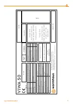
VIW

A

 50

1015 18

I 2H (20 MB

AR)

AT

, BG, CH, CZ, DK, EE, ES, FI, GB

, GR, HR, IE, IT

,

I 2H (20 MB

AR)

LT

, L

V, NO

, P

T, RO

, SE, SI, SK, TR

I 2H (25 MB

AR)

HU 

I 2E (20 MB

AR)

DE, L

U

, PL, RO

I 2E(

S) (20 MB

AR)

BE

The maximum w

at

er pr

es

sur

e PMS:

CH= 4.

0 bar

The elec

trical supply

:

~230 V

A

C (+10%/-

15%) and 50 Hz

The r

at

ed elec

trical po

w

er input:

92

 W

The t

ype of boiler:

Pr

emix C

ondensing Boiler

Hea

t input Qn [kW] (Min/Max

)

6.5 - 50 kW

Maximum w

at

er servic

e pr

es

sur

e CH (PMS

)

4.

0 bar

Pr

ot

ec

tion clas

s:

IP X5D

GC NO

G

as C

at

egories

G20

Maximum hea

t input Qn [kW]

50

Minimum hea

t input Qn [kW]

6.5

Δ

t (80

/60⁰)

Maximum hea

t output Pn [kW]

48.

7

Mi

ni

mum 

he

at

 output

 Pn [

kW]

5.

69

B

23

  C

13

  C

33

  C

53

  C

63


 C

83

I2H / I2E / I2E(

S) - G20 - 20 MB

AR

MET

ANO

NA

TUR

AL GA

S

RE

AD

 THE 

INS

TRUCTION OF


THE B

OILER

 BEF

ORE 

INS

TALL

ATION !!!

RE

AD

 THE 

INS

TRUCTION OF


THE B

OILER

 BEF

ORE 

ST

AR

UP

 THE 

BOILER

 !!!

W

armhaus Isıtma v

e Soğutma Sis

temleri S

an. A.Ş.

Nilüf

er Or

ganiz

e S

ana

yi Bölgesi, Selvi C

adde

, No

: 3

Nilüf

er 16

140

, Bur

sa, T

ürkiy

e

T: +90 22

4 29

5 94 00  F

: +90 22

4 4

11 23 77   in

fo@w

armhaus.

com.

tr

EA

C L

OGO

UKRSEPRO 

LOGO

W

eigh

t: 4

2.

0 k

g

Siz

e: 4

9x81x46 cm

Pr

oduc

tion Da

te

SERİ NO

EAN K

ODU

MADE IN TURKEY

33

Summary of Contents for VIWA 50

Page 1: ...WALL MOUNTED CONDENSING BOILERS INSTALLATION USER MANUAL VIWA50 VIWA65...

Page 2: ...Viwa 50 Viwa 65...

Page 3: ...5 Use Of Split Flue Type Hermetic 2 2 16 Installation At Partially Protected Outsides 2 2 17 Electrical Connections 2 2 18 Optional Controls Room Thermostat Outside Temperature Sensor And Others 2 3 H...

Page 4: ...ed boiler Only APPROVED ORIGINAL spare parts should be used Bolts sealed with paint strictly forbidden to open The boiler must not be used by children younger 8 years or invalid persons without superv...

Page 5: ...Lawa Plus 150 11 606 000001 0 3 mm 30 120 mm 0 2 mm 6 30 mm mza E B NER TA DEM R Logo Kodu Aksi belirtilmeyen genel tolerans i in ISO 2768 M ge erlidir 0 8mm 400 1000 mm 0 5mm 120 400 mm 0 125 mm 3 6...

Page 6: ...r G25 Not Approved Approved Approved Not Approved BE FR YES I 2L Natural Gas 25 mbar G25 Not Approved Approved Approved Not Approved NL YES I 2ELL Natural Gas 20 mbar G20 Not Approved Approved Approve...

Page 7: ...boiler is to be mounted over the kitchen countertop or kitchen set there shall be a minimum 50 cm distance under the boiler Due to possibility of water draining from the Safety Valve of the boiler aft...

Page 8: ...e carefully controlled and will impact the boiler strength Ensure that gas valve connection is correct Flammable gas supply pipe should be able to supply correct adequate gas amount to the boiler when...

Page 9: ...and is thoroughly vented Check that the circulating pump is not jammed Purge the system bleeding off the air present in the gas pipe by operating the pressure relief valve on the gas valve inlet 2 1...

Page 10: ...esh Air Intake with Split Flue Sets Air Exhaust Gas B23 C13 Figure 10 Hermetic Concentric and Flue Split Flue type 2 1 10 Peripheral Distances of the Flue Outlet Connections For positioning of the flu...

Page 11: ...m 32 C at mid level 1 5 m above the floor level 40 C at ceiling level 0 100 mm from ceiling When installed as a class B appliance open flued not roomed sealed Installed in a room High level within 15...

Page 12: ...pe shall be secured with dowels and bracelets with 3 meter intervals 1 90 bend 2 Sealing ring 3 Sealing ring 4 Centering wire 5 External flue pipe 6 Inner wall flange 7 Outer wall flange 8 External fl...

Page 13: ...end equivalent length L5 1 0 m L6 2 0 m L Total 6 3 m 6 3 m Lmax 11 m It is correct in implementation Implementation L1 0 5 m L2 1 0 m 90 bend equivalent length L3 1 5 m L4 1 0 m 90 bend equivalent le...

Page 14: ...e L 500 mm 153 11 660 600026 80 125 Extension Flue L 1000 mm 153 11 660 600027 80 125 Extension Flue L 1500 mm 153 11 660 600028 80 125 Extension Flue L 2000 mm 153 11 660 600029 80 125 Bend 45 153 11...

Page 15: ...individual in accordance with directives and standards in force in the country where the boiler is installed Also ensure that the electricity installation complies with the maximum power to be supplie...

Page 16: ...r drainage of water into to the installation place when the safety valve is enabled 2 2 3 Drainage of the Condensate Water The appliance shall be connected to the drainage water network through pipes...

Page 17: ...drainage pipe outlet Open air flusher Figure 32 Outside Connection of Condensate Water Drainage Pipe SECTION 2 INS Outdoor flusher Condensate Water Drainage Pump Refer to detailed instructions of the...

Page 18: ...te exchanger at least one expansion tank must be placed in the return line of the cascade side and the return line of the heating system side Filter elements strainers must be fitted to return line of...

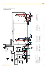
Page 19: ...ection 3 x 1 0 mm 2 2 Boiler Slave 1 Boiler Master 6 Boiler Slave INSTALLATION EQUIPMENT 1 Boiler 2 Gas Safety Solenoid Valve 3 Ball Valve 4 Gas Filter 5 Vibration Isolator 6 Condensate Water Siphon a...

Page 20: ...s and eventual copies The content of this document is Bertelli Partners s r l s property You must not be copy or use it in whole or in part without a prior written consent by Bertelli Partn 0 MLC27 1...

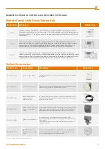
Page 21: ...ture Sensor with Cable It is the sensor that notifies the maximum flow water temperature by measuring the outside air temperature It is necessary to use one for fuel economy in single boiler or cascad...

Page 22: ...ler heating and domestic hot water Leave the boiler in Stand by OFF on the display position thus Anti Frost Function will be enabled Turn off the boiler during maintenance and repair operations near t...

Page 23: ...oiler operates only for domestic hot water in this mode if a boiler is fitted To switch to domestic water position 3 2 4 Resetting the Boiler Restart When the appliance shows fault blocking error push...

Page 24: ...set with no 7 and 8 buttons and this temperature is shown on this display with no 10 indicator for Heating system and no 12 indicator for Hot Domestic Water Turning off the Boiler To turn off the boil...

Page 25: ...to the curves given below After connecting the Outside Temperature Sensor by means of the P04 parameter It is adjusted according to average outside temperature of your province This setting will be p...

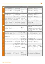
Page 26: ...ton and check if problem is solved 2 Check if the boiler heating system valves are open if not open all of them 3 Check if all radiator valves are open if not open minimum 3 meter radiators must be on...

Page 27: ...ed 2 Check if the boiler heating system valves are open if not open all of them 3 Check if all radiator valves are open if not open minimum 3 meter radiators must be on 4 Restart the boiler by pushing...

Page 28: ...e authorized service if fault remains unsolved E 79 Minimum regulating current value is reached The boiler does not operate E79 error code blinks Gas Supply Pressure Wearing or corrosion of electrode...

Page 29: ...ode position Burning calibration Gas valve fault Electronic board 1 Call the authorized service first 2 Check for false flue OR flue gas clogging 3 Restart the boiler by pushing RESET button 2 Call Au...

Page 30: ...TION FOR GUARANTEE CONDITIONS This warranty provided by WARMHAUS does not include fixing or eliminating faults caused by use of the appliance for purposes other than intended use as well as the condit...

Page 31: ...n max C 25 47 25 47 Operating Pressure Maximum bar 4 4 Operating Pressure Minimum bar 0 5 0 5 Temperature Setting Range Temperature Setting Range C 35 60 35 60 Electrical Circuit Power Supply V AC 50...

Page 32: ...t and high temperature regime 2 4 88 87 8 Useful efficiency at 30 of rated heat output and low temperature regime 1 1 97 11 97 39 Auxiliary Electricity Consumption Full load elmax kW 0 09 0 10 Part lo...

Page 33: ...IP X5D GC NO Gas Categories G20 Maximum heat input Qn kW 50 Minimum heat input Qn kW 6 5 t 80 60 Maximum heat output Pn kW 48 7 Minimum heat output Pn kW 5 69 B 23 C 13 C 33 C 53 C 63 C 83 I2H I2E I2E...

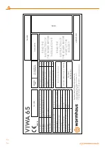
Page 34: ...s IP X5D GC NO Gas Categories G20 Maximum heat input Qn kW 65 Minimum heat input Qn kW 8 t 50 30 Maximum heat output Pn kW 63 2 Minimum heat output Pn kW 7 29 B 23 C 13 C 33 C 53 C 63 C 83 I2H I2E I2E...

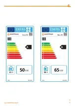
Page 35: ...50 61 Viwa 50 65 58 Viwa 65 35 35...

Page 36: ...VIWA50 VIWA65 WALL MOUNTED CONDENSING BOILERS INSTALLATION AND USER MANUAL VIWA 50 VIWA 65 Montaj Kullan m K lavuzu kodu 150 11 606 000037 Revizyon numaras R02 05 10 2018...

Reviews: