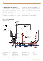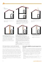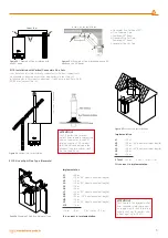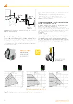
Figure 13
Hermetic vertical split flue connection.
Figure 11
Hermetic concentric and vertical split
flue connection.
Figure 12
Vertical Type Hermetic Use with
Split Flue Set
Figure 14
Building chimney connection with hermetic split flue
Figure 15
Use with split flue set
C
33
C
53
C
53
C
83
C
Discharge with homocentric flue connection
Discharge to building chimney and fresh
air intake with split flue connection
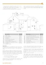
For room sealed appliances of the type C8 boilers
a) overheat combustion products temperature; < 105 C°
b) CO2-content; 9.00 % ( tol%0,5 / -0,5 % )
c) characteristics of the chimney to which the
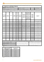
boiler may be connected, according to fig 13.
d) condensate flow into the appliance is not allowed.
Exhaust gas discharge through the building chimney and fresh
intake from outside with split flue sets
For room sealed appliances of the type C6 boilers
overheat combustion products temperature for flue; < 105 °C
CO
2
content at nominal operating conditions; 9.00 % (tolerance
+%0,5 / -0,5 % ) maximum allowable draught and maximum
allowable pressure difference between combustion air inlet and
flue gas outlet (including wind pressures); 120 Pa. characteristics
and the applications of the duct system to which the boiler
can be connected; condensate flow into the appliance is not
allowed. Maximum allowable temperature of combustion air;
40 C° maximum allowable recirculation rate of 10 % under wind
conditions.
Attention:
The terminals for the supply of combustion air and for
the evacuation of combustion products shall not be installed on
opposite walls of the building.
Exhaust gas discharge through the
building chimney and fresh intake
from outside with split flue sets
Exhaust gas discharge and fresh air intake
with concentric flue kit and split flue kits
For room sealed appliances of the type C5 boilers
Attention:
The terminals for the supply of combustion
air and for the evacuation of combustion products
shall not be installed on opposite walls of the building.
Exhaust Gas Discharge Fresh Air
Intake with Split Flue Sets
Air
Exhaust Gas
B
2
3
C
13
Figure 10
Hermetic (Concentric) and Flue
(Split-Flue type
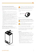
2.1.10. Peripheral Distances of the Flue Outlet Connections
For positioning of the flue set outlet pipe, see Figure 16. The flue shall
be installed in accordance with the national and local regulations.
No part of the outlet pipe or connections shall be blocked. If the
outlet pipe passes1000 mm nearby of a plastic or painted groove or
500 mm of painted fringes, an aluminum shield with at least 1000mm
length shall be placed below the groove or fringe. Outlet pipe shall
be at least 2 m over surfaces within reach by individuals. Under certain
weather conditions, outlet pipe may emit water vapor; installation shall
not be performed at places where this vapor may cause discomfort.
Exhaust gases shall be prevented from entering flue ventilation spaces.
Flue system of combi may be installed from inside the room without
requiring intervention from the external wall. For that reason, an
enclosure shall be installed in the wall for lining the internal surface of
channel wherein the outlet pipe passes through the wall, particularly
for thick walls.
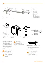
2.1.11. Installation with (Ø80/125 mm) horizontal homocentric flue
sets Connection of (Ø80/125 mm) horizontal homocentric flue set
to the boiler
Since your boiler is a hermetic model, it takes the used air from outside and
discharges exhaust gases created as the result of burning through the same
flue group. In order to prevent emission of extremely harmful exhaust gases,
flue usage and installation is very important, therefore warnings should be
taken into consideration when flue connections are being performed.
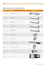
• Carry out required flue selection for the external flue connection. If
the standard flue set is not adequate, please select most suitable
components from our list of connection accessories considering
warnings given in our user guide.
Select the most suitable components by also considering our
warnings.
• Fix the flange under the Bend piece (1) by using the Flange Bolt (10)
Flange Connection Screws (11) to holes on the boiler.
(10) secure it with Flange Connection Screws (11) onto the holes on
the boiler.
10


