18
warmhaus.com
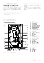
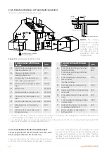
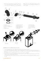
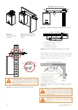
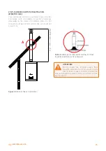
1.
Flue Outlet
2. Flue Gas NTC Sensor
3. Main PCB Panel
4. CH Flow NTC Sensor
5. Air Gas Mixing Unit (AGM)
6. MMI Touch Control Panel
7. CH Outlet (Flow) Pipe
8. 3-Bar Safety Valve
9. Condansation Water Trap
10. DHW NTC Sensor
11. Condansate Drain
12. CH Outlet (Flow)
13. Condansate Cleanable Cup
14. Filling Valve
15. DHW Outlet
16. Gas Inlet
17. Flue Condensation Pan
18. Expansion Vessel
19. Main Heat Exchanger
20. Flame Inspection Glass
21. Ignition Electrode
22. Return Pipe
23. Electronic Fan
24. Plate Heat Exchanger
25. Expansion Tank Air Valve
26. Automatic Air Vent
27. 3 Way Valve
28. Low Pressure Sensor
29. Electronic Pump
30. Gas Valve
31. CH Drain
32. CH Return Inlet
33. DHW Filter
34. DHW Inlet
1
3
4
5
6
7
8
10
14
2
18
20
21
24
26
29
30
31
32
34
19
15 16
13
33
9
11
12
23
27
28
25
17
22
Figure 23
Components of Combi Boiler
2.4. CONTROLS FOR INITIAL
OPERATION OF COMBI BOILER
In order to keep the combi boiler within scope of warranty;
first start must be performed by Warmhaus Authorized
Service. Below given initial preparations should be
performed prior to authorized service appointment
request:
- Gas opening approval certificate should be taken from
the local gas company for your gas line,
- Combi boiler electricity connection should be made via
2 or 3 Amps fuse.
- Ensure that no electricity interruption is available at
your home.
- Ensure that no grid water interruption is available at
your home.
- Ensure that water is supplied to radiator installation
and 1,2 - 1,5 bar pressure is seen in the combi boiler
manometer.
2.5. COMBI COMPONENTS


