


16
warmhaus.com
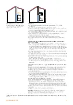
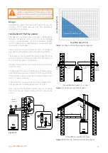
grid should be made as preventing frost of the liquid
contained in the connection installation. Prior to starting
the device, ensure that the condensation water is
correctly discharged; then verify that the siphon is filled
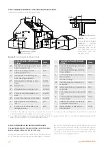
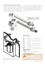
Figure 12
Combi boiler general installation scheme
27
Installation and Servicing
SECTION 2 - INSTALLATION
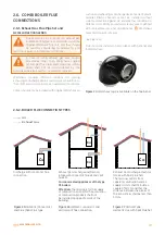
Outdoor flusher
Condensate Water Drainage Pump
(Refer to detailed instructions of the pump manufacturer)
Min Ø 19 mm
Inner
Pipe
75
Min Ø 19 mm
Inner pipe
Min Ø 30 mm
Inner pipe
Air hole
Combined waster
and rain water
drainage pipe
43 mm 90º
male/female bend
Water / Air
proof
insulation
68 mm Ø PVCU
Fitting
Min Ø 19 mm
Min Ø 30 mm
Drainage pipe with water
and air insulation
Maximum length of
the outer pipe
shall be 3 m.
Insert the drainage pipe
at least 25 mm into the tube
located outdoors
Pebble
≥ 500
≥ 25
Required
distance for
minimum 3-storey
buildings
Drainage and
Ventilation Pipe
Min Ø 19 mm
Water / Air proof
insulation
Outdoor flusher
Min Ø 19 mm
Inner pipe
75 mm flusher
bathroom/shower
drainage combined
with other drainage
lines
Minimum 30 mm
Inner pipe
Water / Air
proof
insulation
≥ 25 Distance under grid
45º pipe
termination
75
≥ 100
Figure 2.25
Connection of a Condensate Pump Typical
Method (see manufacturers detailed instructions)
Figure 2.26
Connection of condensate Drainage Pipe to
External Soil & Vent Stack
Figure 2.27
Connection of a Condensate Drainage Pipe to an
External Rainwater Downpipe (only combined foul/rainwater
drain)
Figure 2.29
Connection of a Condensate Drainage Pipe to an
External Purpose Made Soak Away.
Figure 2.28
Connection of Condensate Drainage Pipe
Upstream of a Sink, Basin, Bath or Shower Waste Trap to
External Drain, Gulley or Rainwater Hopper
INS
T
ALL
A
TION
CONDENSATE............ CONT’D
45º cross-
sectional drainage
pipe outlet
Open air flusher
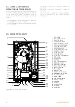
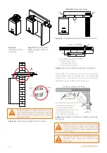
Figure 15
Outside Connection of Condensate Water
Drainage Pipe
27
Installation and Servicing
SECTION 2 - INSTALLATION
Outdoor flusher
Condensate Water Drainage Pump
(Refer to detailed instructions of the pump manufacturer)
Min Ø 19 mm
Inner
Pipe
75
Min Ø 19 mm
Inner pipe
Min Ø 30 mm
Inner pipe
Air hole
Combined waster
and rain water
drainage pipe
43 mm 90º
male/female bend
Water / Air
proof
insulation
68 mm Ø PVCU
Fitting
Min Ø 19 mm
Min Ø 30 mm
Drainage pipe with water
and air insulation
Maximum length of
the outer pipe
shall be 3 m.
Insert the drainage pipe
at least 25 mm into the tube
located outdoors
Pebble
≥ 500
≥ 25
Required
distance for
minimum 3-storey
buildings
Drainage and
Ventilation Pipe
Min Ø 19 mm
Water / Air proof
insulation
Outdoor flusher
Min Ø 19 mm
Inner pipe
75 mm flusher
bathroom/shower
drainage combined
with other drainage
lines
Minimum 30 mm
Inner pipe
Water / Air
proof
insulation
≥ 25 Distance under grid
45º pipe
termination
75
≥ 100
Figure 2.25
Connection of a Condensate Pump Typical
Method (see manufacturers detailed instructions)
Figure 2.26
Connection of condensate Drainage Pipe to
External Soil & Vent Stack
Figure 2.27
Connection of a Condensate Drainage Pipe to an
External Rainwater Downpipe (only combined foul/rainwater
drain)
Figure 2.29
Connection of a Condensate Drainage Pipe to an
External Purpose Made Soak Away.
Figure 2.28
Connection of Condensate Drainage Pipe
Upstream of a Sink, Basin, Bath or Shower Waste Trap to
External Drain, Gulley or Rainwater Hopper
INS
T
ALL
A
TION
CONDENSATE............ CONT’D
45º cross-
sectional drainage
pipe outlet
Open air flusher
Figure 16
Typical Connection Method of a Condensate
Water Drainage Pipe (refer to detailed instructions of
the pump manufacturer)
Min Ø 19 mm
Min Ø 19 mm
Drainage and Ventilation Pipe
≥ 100
Figure 2.23
Connection of Condensate Drainage Pipe to
Internal Soil & Vent Stack
Figure 2.24
Connection of a Condensate Drainage Pipe
Downstream of a Sink, Basin, Bath or Shower Water Trap to
Internal Soil Vent Stack
Minimum
connection
height
up to 3
storeys
Sink/basin/
bath or
shower
Drainage and Ventilation Pipe
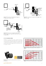
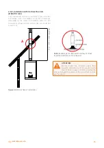
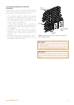
Figure 13
Connection of the Condensate Water Drainage
Pipe to Internal Drainage and Ventilation Pipe
Min Ø 19 mm
Min Ø 19 mm
Drainage and Ventilation Pipe
≥ 100
Figure 2.23
Connection of Condensate Drainage Pipe to
Internal Soil & Vent Stack
Figure 2.24
Connection of a Condensate Drainage Pipe
Downstream of a Sink, Basin, Bath or Shower Water Trap to
Internal Soil Vent Stack
Minimum
connection
height
up to 3
storeys
Sink/basin/
bath or
shower
Drainage and Ventilation Pipe
Figure 14
Connection of Condensate Water Drainage
Pipe at Indoor Bathroom Drainage Lower Level
through condensation at first start (parag. 2.2.10). Also,
instructions in force, national and local arrangements
should be taken into consideration for discharge of waste
waters.
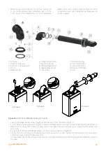
Heating Return (cold)
City water line
Heating
Flow
(hot)
Condensation
water outlet