background image

SAFETY


CHECK


LIST


DON’T


TAKE


UNNECESSARY


RISKS!


Failure to read and apply manual instruc ons will cause poor performance, unnecessary repairs and injury. 

Wear


safety


glasses,


hearing


protec on


and


respiratory


protec on.


Disconnect


the


power


before


servicing


or


changing


knives.


Wear


footwear


that


does


not


slip.


This


will


help


you


keep


proper


foo ng


and


balance.


Always


stand


beside


the


machine,


never


in


the


way


of


the


in

feed


and


out

feed


areas.


Keep


knives


sharp


and


clean.


Make


sure


the


machine


has


proper


grounding.


Make


sure


all


guards


are


secured


and


in


working


order.


Remove


all


adjus ng


keys


and


wrenches


before


star ng.


Check


the


stock


for


loose


knots,


nails,


and


foreign


ma er.


Keep


the


machine


in


a


dry,


clean,


and


well

lit


area.


PREPARING TO USE THE MACHINE 

1.


Disconnect


the


power


source


while


going


through


these


procedures.


2.


Check


knives


to


ensure


that


the


bolts


are


ght.


If


molding,


set


your


guides


for


the


stock


path


through


the


knife


area.


If


plaining,


you


may


or


may


not


wish


to


set


your


guides.


Many


mes,


they


are


not


needed


in


plaining.


3.


When


molding,


the


head


scale


se ng


must


be


set


to


within


3/16”


of


the


height


of


your


stock

.


The


“0”


on


your


scale


is


set


to


the


top


of


your


GS

2


guide


system


sub

plate.


This


means


you


would


set


the


machine


head


reference


to


the


scale


at


¾”


in


order


to


take


a


full


pro

fi

le


pass


on


a


¾”


piece


of


stock.


You


could


set


the


machine


head


in


reference


to


the


scale


at


15/16”


for


a


maximum


height


fi

rst


pass


(3/4”


+


3/16”).


This


se ng


will


provide


the


proper


roller


tension.


Any


other


se ng


higher


from


the


thickness


of


the


stock


entering


the


machine


is


unacceptable


and


dangerous.


See


the


molding


sec on


for


more


informa on.


4


The


chip


extractor


loads


fi

rst


under


the


out

feed


end


of


the


head


with


a


lip


under


the


cast


head.


You


then


fi

nish


by


a aching


the


chip


extractor


with


its


pin.


Make


sure


the


pin


is


inserted


all


the


way


in


un l


you


feel


it


“catch”


on


the


spring

loaded


catch.


5.


Check


rota onal


clearance


of


the


knife


with


the


chip


extractor


in


place.


Rotate


the


knife


by


hand


at


the


5”


pulley


cut


out


on


the


inner


belt


guard


to


ensure


the


knife


area


is


clear.


6.


Do


not


stand


or


let


others


stand


in


the


out

feed


area


or


directly


in


line


with


the


in

feed


of


the


machine.


7.


With


the


head


set


in


the


proper


posi on,


ghten


the


head


locking


bolt


fi

rmly.


This


is


essen al


for


safety


and


to


ensure


the


machine


head


will


stay


where


you


have


set


it.


8.


Test


a


piece


of


stock,


with


the


machine


o

,


to


see


if


it


will


make


contact


with


the


in

feed


roller.


Summary of Contents for 20210492060001

Page 1: ...entative maintenance and other pertinent data to assist you in assuring long life and dependable service from your machine Molder Model 206 208 230 1 v2 0 206 208 230 3 v2 0 For Serial numbers 2021049...

Page 2: ...ect and cau on Following stated and inherent safety precau ons will considerably lessen the possibility of personal injury If normal safety measures are not taken or are overlooked the possibility of...

Page 3: ...ock The 0 on your scale is set to the top of your GS 2 guide system sub plate This means you would set the machine head reference to the scale at in order to take a full profile pass on a piece of sto...

Page 4: ...side covers Cut the zip tie around the motor Remove the motor shipping boards Remove the lag bolts holding the machine to the pallet Lift the machine off of the pallet Re install the sides Before elev...

Page 5: ...lure to do so will damage the control panel If you facility does not have a wild leg connect as per diagram If your machine is rota ng the incorrect way switch only the black and red wires green is gr...

Page 6: ...ll start and stop the cu er head Speed Dial will control the speed of the feed rollers 0 is stop 10 is fastest E Stop Start Stop Speed Dial Magne c Starter assembly Double pole fuse holder and Line fu...

Page 7: ...under the out feed roller before engaging a higher feed rate This reduces the inci dence of a large chip out a cha er mark or snipe on the first few inches of your stock You have the same advantages e...

Page 8: ...um edge loss return your knives to the factory for re sharpening Have your knives re sharpened when you first no ce some dullness This gives op mal performance and maximum life span out of the knives...

Page 9: ...e bolts in the direc on of the tube side of the machine for an exact profile match up Hold secure while ghtening bolts Set the head height to within 3 16 of your stock height This will give you proper...

Page 10: ...g the stock out from the bed Your knives will usually cut into one or both guides This is normal and expected The guides are e ec ve and last a long me a er being cut into many mes As you become more...

Page 11: ...the angle needed to cut the wood sec ons in order to stay within the selected radius Lay out the wood sec ons by marking the angles while being careful to select cuts for grain structure and color Cu...

Page 12: ...ht Rotate the blade arbor by hand to insure nothing is interfering with its rota onal path Mould the panel cross grain ends first Stand somewhere between the open side and in feed side RAISED PANEL IS...

Page 13: ...planing the edge of stock to ensure the edge will be reasonably square A relief in the ver cal wall of the guide reduces fric on See the guide sec on for a picture of the edge guides THREAD LOCKING IN...

Page 14: ...generally an unwanted undercut in the stock It occurs in the first and last few inches of the stock length It causes a di erent height di mension than what was selected for the stock Causes The stock...

Page 15: ...lers to see if they have a glossier than normal build up Clean the gloss or pitch build up o the rollers Make sure adequate spring pressure is being ap plied to the rollers Check the base or bed for r...

Page 16: ...he roller Reset the roller in a vise and use a small pipe wrench to remove it from the roller REASSEMBLY The rollers are constructed with a shallow hole in one end and a deeper hole in the other The P...

Page 17: ...a small amount of slack in it and the long out feed chain should have plenty of slack This is the correct se ng To obtain the correct se ng in most cases you would push the unit toward the in feed end...

Page 18: ...olt holding the chain guard to the machine head As you pull the unit free pull off the in feed chain sprocket you loosened To remove the motor from the motor mount and chain guard remove the two motor...

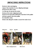
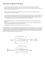
Page 19: ...ARBOR REMOVAL VIEW...

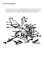
Page 20: ...Stand exploded diagram...

Page 21: ...age due to modifica ons misuse improper maintenance normal wear wood jams or using a knife motor with a horsepower ra ng over 2HP WHO IS COVERED The warranty covers the ini al purchaser only LIMITATIO...

Page 22: ...Notes Maintenance Records...

Page 23: ...ine replacement parts For parts please call customer service or log onto our website Printed in the USA Williams Hussey 04 2021 Molder update 4 21 2021 Update model numbers 5 3 21 update9 30 21 added...

Reviews: