Operating Manual WLVCM-BA-10
Page 31 of 37
EN
Once a set of parameters was read from or transferred into the WLVCM, the currentness
of each parameter – for heating as well as for application parameters – will be indicated by
the symbol to the left.
If you make changes to the parameters in the configuration tool WLVCM, the parameter
group which you change will delete the symbol. You will then notice that the current
configuration of heating and application parameters in the configuration tool is differing
from the saved configuration in the WLVCM module.
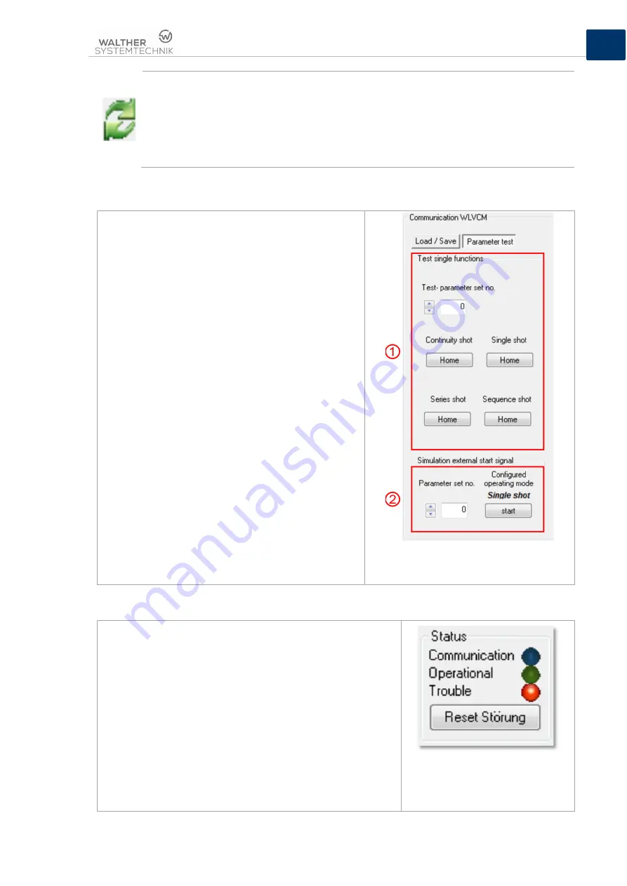
8.4.11 Test of Parameters
Use the area “Parameter test“ for testing pre-
configured parameters and parameter sets. Before you
can actually perform a parameter test it is necessary to
transfer the testing parameters or parameter sets into
the WLVCM, as described in chapter 8.5.1.
In subsection
➀
(see figure 15) it is possible to test
individual functions with the parameters of a previously
selected parameter set. Select the testing parameter
set from the field “Test parameter set no.“. As soon as
you clicked on the respective “start” button the
individual function “single”, “continuity”, “series” or
“sequence” shot will be carried out.
Above that, with the subsection parameter test it is
possible to simulate an external trigger event at the
clamps „Start -“ and „Start +“ (see also
➁
in figure 15).
Here too, you have to select a parameter set for
activating the corresponding operating mode for this
parameter set. When you have selected the parameter
set from the field “Parameter set no.“
➁
, also the
connected operating mode for this set of parameters
will be indicated in subsection
➁
. Simply click on the
“Start“ button and the operating mode connected to
this set of parameters will be directly activated.
In the case of a configured “permanent signal“-trigger
event, the button “Start“ will change its description to
“Stop“. Another click on this button will stop the
simulated permanent signal and the application
process stops.
Figure 16 – Options for testing parameters
and parameter sets
8.5 Configuration Tool WLVCM – Area Status
The area “Status“ (see also figure 6) gives the user an
overview of the current system status of the WLVCM module.
The “blue“ signal lamp “Communication“ indicates the active
data exchange between configuration tool and WLVCM
module.
The lamp “Operational“ indicates that the device is ready for
operation. It is directly connected to the digital outlet “Ready“
and the LED “Ready for start“!
The “Trouble“ lamp indicates a malfunction. The lamp is
coupled with the digital outlet “Error“. When a malfunction
occurs, as depicted in figure 16, the “Reset malfunction”
button will be displayed in the “Status” area. Use this button to
reset/confirm an active malfunction. The function of the button
is similar to the digital inlet signal “Reset”.
Figure 17 – Elements for status
Summary of Contents for WLVCM
Page 37: ...Article Number WLVCM BA 10...


