


OPERATOR’S MANUAL
4. For drop-thru style airlocks, inspect the outlet seal as follows:
a. With reference to the auxiliary equipment’s operator’s manual, remove any
components connected to the airlock outlet.
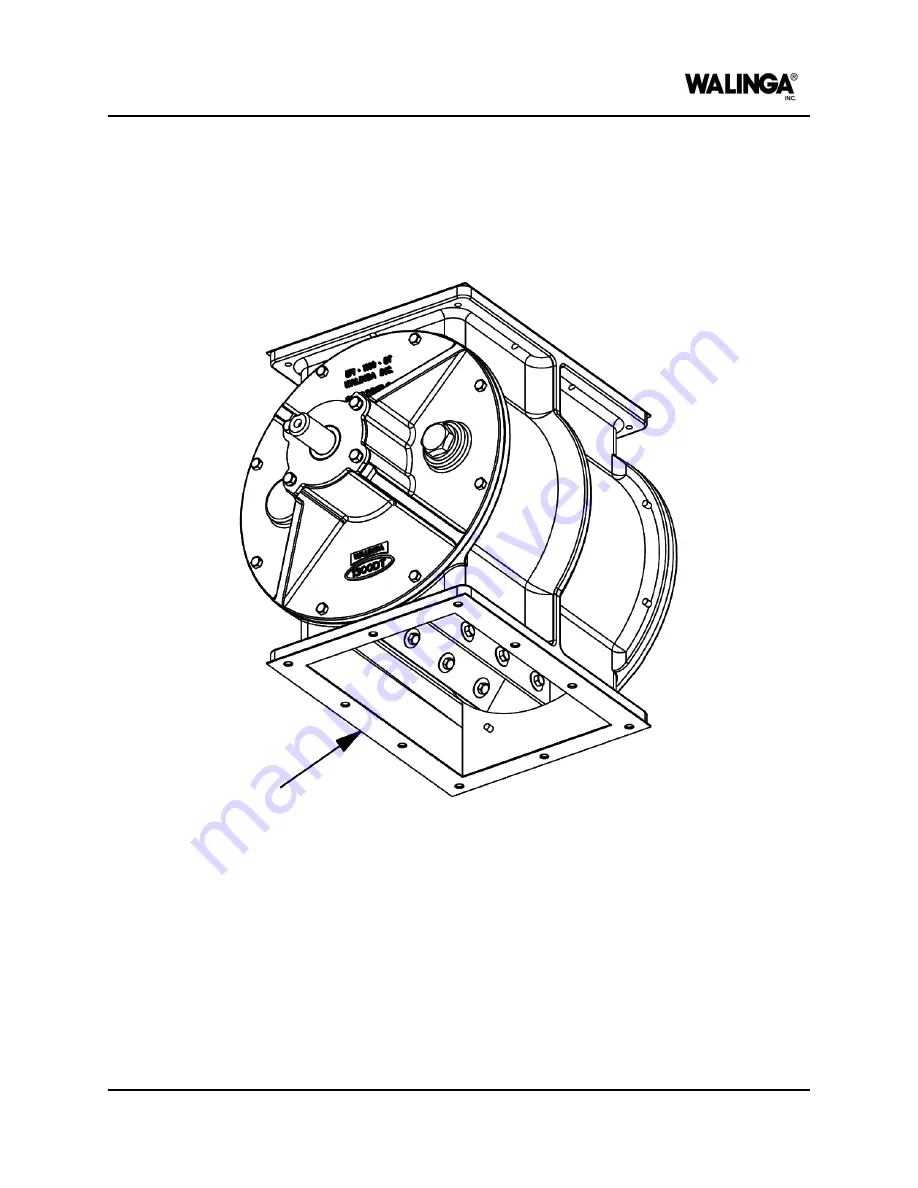
b. Visually inspect the seal, looking for any nicks, tears, abraded areas, excessive
wear, or accumulation of dirt, dust or debris.
Figure 7-22: Drop-thru outlet seal
c. Clean or replace the seal as required.
d. Reinstall any components that were removed and ensure all guards are installed
and secured.
5. For blow-though style airlocks, inspect the outlet seals as follows:
a. With reference to the auxiliary equipment’s operator’s manual, remove any
components, including adapters and reducers, connected to the airlock outlet.
MAINTENANCE AND ADJUSTMENTS
00-144477-0 A
7-23
Summary of Contents for Airlock 1008
Page 1: ...OPERATOR S MANUAL Airlock 1008 English 00 144471 0 A 2023 12 06...
Page 7: ...Identification of Machine AIRLOCK MODELS 1 1...
Page 9: ...Introduction AIRLOCK MODELS 2 1...
Page 15: ...Machine Configuration AIRLOCK MODELS 3 1...
Page 26: ...OPERATOR S MANUAL PAGE INTENTIONALLY LEFT BLANK 3 12 00 144473 0 A MACHINE CONFIGURATION...
Page 27: ...Safety AIRLOCK MODELS 4 1...
Page 39: ...Machine Life Cycle Procedures AIRLOCK MODELS 5 1...
Page 45: ...Operation AIRLOCK MODELS 6 1...
Page 54: ...OPERATOR S MANUAL PAGE INTENTIONALLY LEFT BLANK 6 10 00 144476 0 A OPERATION...
Page 55: ...Maintenance and Adjustments AIRLOCK MODELS 7 1...
Page 99: ...Specifications AIRLOCK MODELS 8 1...
Page 108: ...OPERATOR S MANUAL PAGE INTENTIONALLY LEFT BLANK 8 10 00 144478 0 A SPECIFICATIONS...
Page 109: ...Warranty AFTERMARKET PARTS AND SERVICE 9 1...
Page 113: ...Accessories and Attachments AIRLOCK MODELS 10 1...
Page 116: ...OPERATOR S MANUAL PAGE INTENTIONALLY LEFT BLANK 10 4 00 144480 0 A ACCESSORIES AND ATTACHMENTS...
Page 117: ...Parts List AIRLOCK 1008 MODEL 11 1...
Page 125: ...PAGE INTENTIONALLY LEFT BLANK...


