1 2
Installation for Rolling Test
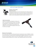
Undo the clamp bolt and nut and remove the extension handle. The magnetic clamp assembly
will also separate from sensor head.
Reinstall the magnetic clamp assembly directly to the sensor head.
If the exhaust stack is equipped with an exhaust flapper, remove the flapper cover assembly. If
this is not practical, tighten the hinge bolt on the flapper cover assembly to maintain the flapper
in its maximum open position.
Install sensor head assembly on exhaust stack, using the magnetic clamp assembly. (See
above and SAE J1667 document for instructions). Secure the unit with locking pin.
For actual road tests, you may need to adjust the sensor head assembly, so that the
measurement is not affected when the vehicle is in motion.
Follow Mode Test
The “Follow” mode provides a means of providing a continuous “real life” opacity reading and
performing tests under load, either on the road or on a dynamometer.
Follow the instructions listed in Installation Sections for attaching the sensor head to the stack
of the vehicle. Make a special point of securing the sensor head if a road test is performed.
Press the ON/OFF button on the control unit. The unit will perform a self-calibration.
Press the SELECT button until the desired stack size is displayed (factory default is 5”). Press
the SAVE button.
The HP shown corresponds to the default horsepower. If your engine has different
specifications, press SELECT until the correct value is displayed. Press SAVE.
Press the START TEST button.
Follow your state’s test requirements as to RPM and load factors.
When you have reached the governed load, press SAVE.


